- Have any Query
- (303) 807-1061
- doug@servohydraulicsolutions.com
Large Hydraulic Shaker Table Procurement Guide: Sizing Overturning Moment, Reaction Mass & Actuator Force

Servo-Hydraulic vs Electrodynamic & Motorized Shake Tables: Which Vibration Table Fits High-Payload Testing?
November 12, 2026
Pit-Mounted vs Free-Standing Buttress Shake Tables: Facility Cost, Access & Foundation Comparison Guide
November 13, 2026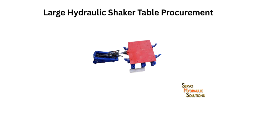
Earthquake simulation shake table prices range from 653–3,000 for small open-source educational stepper platforms and 15,000–45,000 for entry-level commercial units, while custom high-payload servo-hydraulic shake tables typically require custom engineering quotes starting from tens of thousands to several hundred thousand dollars depending on payload, axes (uniaxial vs. multi-DOF), and Hydraulic Power Supply (HPU) capacity. Choosing an open-architecture COTS servo-hydraulic system allows university and commercial labs to match real seismic velocity and force requirements without paying proprietary OEM markups.
A large hydraulic shaker table must be designed around more than the weight of the specimen it will carry. For reliable heavy-specimen seismic testing, buyers need to evaluate actuator force, stroke, velocity, overturning moment, reaction mass, and foundation capacity as one connected system. Getting these specifications right before procurement helps avoid performance limitations, costly modifications, and installation problems later.
This guide explains the main engineering checks involved in selecting a high-payload hydraulic shake table, with practical calculations and a worked example to help laboratories prepare a useful technical specification.
What Is a Large Hydraulic Shaker Table?
A large hydraulic shaker table is a servo-hydraulic testing platform designed to reproduce controlled vibration and seismic motion while carrying heavy specimens. It uses hydraulic actuators to move a test platform, with a controller and feedback sensors regulating the motion.
A typical system includes:
- A rigid moving platform and supporting structure.
- Hydraulic actuators to generate movement.
- Servo valves to control hydraulic flow.
- A hydraulic power unit (HPU).
- A digital controller and feedback sensors.
- A reaction structure and suitable foundation.
- Fixtures and mounting arrangements for the specimen.
The system may be designed for one, two, or multiple motion axes, depending on the testing programme.
How a Large Hydraulic Shake Table Works
The HPU supplies pressurised hydraulic fluid to the actuators. Servo valves regulate the fluid flow and direction, causing the actuator pistons to extend or retract. This moves the table according to the commanded test profile.
Sensors measure the actual movement and send feedback to the controller. The controller compares the measured response with the target signal and adjusts the actuator commands to reduce the difference.
This closed-loop operation is important when testing heavy or tall specimens. The system must reproduce the required motion while managing changing loads and dynamic forces.
When a High-Payload Hydraulic Shake Table Is Needed
A high-payload system matters when conventional vibration equipment cannot provide the required force, displacement, or platform capacity.
Common applications include:
- Seismic qualification of heavy electrical equipment.
- Testing large industrial machinery and equipment cabinets.
- Structural component and connection testing.
- Earthquake simulation for building and infrastructure models.
- Testing heavy mechanical assemblies and support systems.
For example, a laboratory testing a large electrical cabinet must account for the cabinet’s mass, mounting frame, centre of gravity, and required seismic acceleration. Simply choosing a table with a matching payload rating is not enough.
Common applications include seismic qualification of heavy electrical equipment, structural testing, and deploying custom servo-hydraulic shake tables and earthquake simulators designed for demanding facility conditions.
What “Large” Means in Hydraulic Shake Table Specifications
No single payload value defines a large hydraulic shake table. The term depends on the combination of:
- Maximum specimen and fixture mass.
- Table dimensions and moving mass.
- Available actuator force.
- Maximum displacement and velocity.
- Frequency and acceleration performance.
- Allowable overturning moment.
- Reaction mass and foundation capacity.
A table may support a heavy specimen but still be unsuitable for a tall specimen that creates a large overturning moment. Procurement should therefore begin with the complete test requirement, not a single headline specification.
Key Specifications for Heavy Specimen Testing
When comparing high payload hydraulic shake table specs, look at how the main performance limits work together. A table’s maximum payload, for example, may only be available under certain acceleration or frequency conditions.
| Specification | What it tells you | Why it matters |
| Payload | Allowable specimen mass | Confirms load capacity |
| Table size | Available mounting area | Determines specimen fit |
| Moving mass | Total mass accelerated by the system | Affects actuator force |
| Actuator force | Available driving force | Determines acceleration capability |
| Stroke | Maximum actuator or platform travel | Limits displacement |
| Velocity | Maximum movement speed | Affects achievable test profiles |
| Acceleration | Rate of change of velocity | Defines dynamic performance |
| Frequency | Operating vibration range | Determines suitable test applications |
| Overturning moment | Allowable rotational loading | Important for tall and off-centre specimens |
| Motion axes | Directions of movement | Determines test configuration |
Payload, Table Size, and Moving Mass
Payload is the mass of the specimen that the table is designed to support or move under specified operating conditions. Moving mass is broader. It may include the specimen, mounting fixtures, adapter plates, and other components that move with the platform.
Suppose a specimen weighs 10,000 kg and its mounting fixture weighs 1,000 kg. The system must account for at least 11,000 kg of specimen-and-fixture mass, plus any moving table components not included in the manufacturer’s rating.
Table dimensions matter just as much. A specimen may fit within the platform’s length and width but create excessive loading because of its mounting position or centre of gravity.
Actuator Force, Stroke, and Velocity
Actuator force determines how much force the system can apply to accelerate the moving mass. Stroke defines the available travel, while velocity determines how quickly the actuator can move.
These limits must be checked together. A system may achieve its rated force at a particular operating condition but not deliver maximum force, stroke, and velocity simultaneously.
Ask suppliers for performance curves or operating envelopes showing the available force and motion at the intended test frequencies.
Acceleration and Frequency Requirements
Acceleration is usually specified in units of m/s² or as a multiple of gravitational acceleration, g. Frequency is measured in hertz (Hz).
A heavy specimen tested at modest acceleration may need less actuator force than a lighter specimen tested at a much higher acceleration.
The required frequency range also affects system selection. Structural earthquake simulation often involves relatively low-frequency motion and substantial displacement, while component vibration tests may require higher frequencies and smaller movement.
Overturning Moment and Off-Centre Loading
Overturning moment is the rotational effect created when horizontal forces act through a specimen’s centre of gravity above the table surface.
Off-centre loading creates an additional moment when the specimen’s centre of gravity is not aligned with the table’s centre or intended load axis.
Both conditions can affect actuator loading, guide systems, bearings, platform stiffness, and foundation design. They should be stated clearly in the procurement specification.
Degrees of Freedom and Motion Axes
A uniaxial table moves along one axis. A biaxial system provides movement in two horizontal directions, while more advanced configurations can include vertical movement and additional rotational degrees of freedom.
More axes can reproduce more complex motion, but they also increase design and control requirements. Actuator arrangement, cross-axis interaction, load distribution, and reaction structure capacity all need to be considered.
Choose the number of axes based on the tests you intend to perform, rather than paying for motion capabilities that will rarely be used.
Calculating Overturning Moment for Shake Tables
Calculating overturning moment for shake tables is essential when testing tall, heavy, or unevenly loaded specimens. A system may have sufficient payload and actuator force but still be unsuitable if the resulting rotational loading exceeds its design limits.
What Is Overturning Moment?
Overturning moment is the tendency of a horizontal force to rotate a specimen or structure around a reference point, such as the table surface.
For a simplified horizontal loading condition:
Overturning moment = Horizontal force × Effective height
Since horizontal force can be estimated using mass multiplied by acceleration:
[
M = m \times a \times h
]
Where:
- (M) = overturning moment in N·m.
- (m) = specimen mass in kg.
- (a) = horizontal acceleration in m/s².
- (h) = effective centre-of-gravity height above the reference point in metres.
This is a preliminary estimate. Detailed design must account for the actual load path, structural flexibility, dynamic response, and relevant design load combinations.
How Specimen Height Affects Overturning Moment
The higher the specimen’s centre of gravity, the larger the overturning moment for the same mass and horizontal acceleration.
Consider two specimens with the same mass and acceleration. If one has a centre of gravity at 1 m and the other at 2 m, the taller specimen produces twice the overturning moment under the simplified calculation.
This is why tall electrical cabinets, equipment racks, and structural assemblies need careful assessment even when their total mass is within the table’s payload rating.
How Horizontal Acceleration Affects Overturning Moment
Overturning moment also increases with horizontal acceleration. Doubling the acceleration doubles the calculated horizontal inertial force and, assuming the same mass and height, doubles the overturning moment.
The design should therefore be checked against the maximum acceleration expected in the test profile, including relevant transient conditions.
Worked Example of Overturning Moment Calculation
Consider a heavy specimen with the following properties:
| Parameter | Value |
| Specimen mass | 10,000 kg |
| Horizontal acceleration | 1 g = 9.81 m/s² |
| Centre-of-gravity height | 2 m |
Step 1: Calculate horizontal inertial force.
[
F = m \times a
]
[
F = 10,000 \times 9.81 = 98,100\ N
]
The horizontal inertial force is 98.1 kN.
Step 2: Calculate the overturning moment.
[
M = F \times h
]
[
M = 98,100 \times 2 = 196,200\ N\cdot m
]
Therefore:
[
\boxed{M = 196.2\ kN\cdot m}
]
The estimated overturning moment is 196.2 kN·m, before considering dynamic amplification, fixture effects, additional eccentricity, or engineering design margins.
This example gives a useful first estimate, not a final foundation or actuator design value. The supplier and structural engineer must verify the actual load cases and load paths.
Why Dynamic Amplification Matters
A specimen does not always behave like a rigid mass. Its natural frequencies, flexibility, damping, and connections can affect the forces transmitted to the table.
If the specimen responds strongly near one of its natural frequencies, internal dynamic forces may exceed what a simple rigid-body estimate suggests. Dynamic analysis or appropriate testing methods may therefore be required.
For tall or flexible specimens, ask the supplier how the allowable overturning moment is defined and whether it accounts for the intended dynamic operating conditions.
Reaction Mass and Shake Table Foundation Design
Reaction mass is a major part of a large hydraulic shaker table installation. It provides the opposing mass and structural support needed to resist actuator forces, helping the table generate the required motion without excessive movement of the supporting structure.
What Is a Reaction Mass?
A reaction mass is a substantial mass, commonly integrated with a reinforced concrete foundation or reaction block, that provides a stable support for the actuator system.
When an actuator pushes the moving table in one direction, an equal and opposite reaction force acts on its supporting structure. The reaction mass and foundation help resist this force.
Without adequate support, unwanted movement or vibration transmission can affect test accuracy and the surrounding facility.
How Reaction Mass Supports Actuator Force
Hydraulic actuators apply force between the moving assembly and the reaction structure. The reaction structure must safely carry the opposing load.
Its performance depends on more than weight. Structural stiffness, anchorage, foundation dimensions, soil or building support conditions, and the frequency content of the applied forces all matter.
A very large reaction mass is not automatically well designed. It must be properly integrated with the foundation and the laboratory structure.
Reaction Mass Size and Foundation Requirements
No universal reaction-mass-to-payload ratio applies to all shake tables. The required mass and foundation arrangement depend on:
- Maximum actuator force and its direction.
- Specimen mass and centre of gravity.
- Expected overturning and lateral loads.
- Operating frequency and duty cycle.
- Allowable foundation movement.
- Soil conditions and nearby building structures.
- Vibration transmission limits.
Large facilities can use reaction masses substantially heavier than the moving payload. For example, a published system specification may describe a 2,350-tonne reaction mass supporting a table with a 140-tonne payload. This is an example of a particular facility design, not a sizing rule that can be applied to every project.
Before procurement, arrange a foundation assessment with the equipment supplier and a qualified structural or geotechnical engineer. The review should cover concrete strength, reinforcement, anchorage, embedded components, vibration transmission, and installation tolerances.
When Vibration Isolation Is Required
Vibration isolation may be needed when testing could transmit unwanted vibration to nearby laboratories, sensitive instruments, or building structures.
The isolation approach depends on the operating frequency, force levels, foundation arrangement, and acceptable vibration limits. In some facilities, a dedicated reaction block and foundation are sufficient; in others, isolation trenches or specialised support arrangements may be considered.
The decision should come from a vibration and structural assessment, not a standard assumption.
Shake Table Actuator Force and Reaction Mass
Actuator force and reaction mass must be considered together. Increasing actuator force without checking the supporting structure can create a new limitation even if the hydraulic system itself has enough capacity.
How Actuator Force Is Sized
The starting point is Newton’s second law:
[
F = m \times a
]
Use the total moving mass and the required acceleration to estimate the ideal inertial force.
For a real system, the calculation must also consider:
- Moving platform and actuator-related mass.
- Fixture and adapter mass.
- Friction and mechanical resistance.
- Dynamic response of the specimen.
- Number and orientation of actuators.
- Multi-axis loading and load distribution.
- Appropriate engineering margins.
The force demand should be evaluated across the full test profile, not only at one peak acceleration value.
How Hydraulic Flow Supports Actuator Force
Hydraulic pressure and actuator piston area determine the theoretical force available from an actuator:
[
F = P \times A
]
Where (P) is the effective pressure difference across the piston and (A) is the effective piston area.
Hydraulic flow is closely related to actuator velocity:
[
Q = A \times v
]
Where (Q) is volumetric flow and (v) is piston velocity.
In practice, the system must also account for pressure losses, leakage, valve capacity, fluid compressibility, and simultaneous actuator demand. Depending on the system design, accumulators may help meet short-duration peak flow requirements.
How Reaction Mass Resists Actuator Force
The reaction structure provides the opposing support needed for actuator operation. It must resist the applied forces without excessive displacement, rotation, or vibration.
Its design should be checked for both static and dynamic load cases. The actuator attachment points, foundation stiffness, and anchorage all contribute to the overall response.
Matching Actuators, Servo Valves, and Hydraulic Supply
The actuator, servo valve, and HPU should be specified as a coordinated system.
- Actuator: Must provide the required force, stroke, and velocity.
- Servo valve: Must deliver the flow and response needed for the target motion.
- HPU: Must provide suitable pressure and continuous flow for the intended duty cycle.
- Cooling system: Must manage heat generated during operation.
- Controller and sensors: Must provide suitable feedback and motion control.
A high-force actuator paired with an undersized valve or an unoptimized custom hydraulic power supplies (HPS) will not deliver the expected performance under full load.
Heavy Specimen Seismic Table Design
A heavy specimen seismic table design should begin with the specimens and tests the laboratory expects to handle. This avoids designing around an impressive payload figure that does not reflect real testing needs.
Define the Specimen and Test Profile
Prepare a list of representative specimens, including their mass, dimensions, centre of gravity, mounting points, and structural characteristics.
For each test, identify:
- Required acceleration and frequency range.
- Horizontal and vertical displacement.
- Velocity requirements.
- Number of motion axes.
- Test duration and repetition.
- Applicable test standards or project specifications.
Calculate Total Moving Mass and Centre of Gravity
Include the specimen, fixtures, adapters, and all moving components. Record the centre of gravity in all relevant directions.
For multiple specimens or mounting configurations, calculate the loading for each arrangement. An asymmetric specimen can produce additional moments even when the total mass is within the table’s rated capacity.
Check Force, Stroke, Velocity, and Frequency
Verify that the system can reproduce the complete test profile at the intended moving mass.
Ask for performance data that shows how force, stroke, and velocity vary with frequency. This is more useful than a list of independent maximum values that may not be achievable at the same time.
Design Fixtures and Mounting Arrangements
Fixtures must be strong and stiff enough to transfer the required loads without unwanted deformation or resonance.
Review bolt patterns, anchorage, specimen orientation, instrumentation access, and the effect of fixture mass on system capacity. A poorly designed fixture can compromise a technically capable shake table.
Include Safety Margins and Future Test Needs
Allow appropriate margins for load variation, dynamic effects, and operating conditions. These should be determined through engineering calculations and supplier recommendations.
If the laboratory expects larger specimens or additional axes in the future, discuss upgrade options before the initial system is built. Some changes can be straightforward; others may require new actuators, a redesigned platform, or foundation modifications.
How to Procure a Large Hydraulic Shaker Table
A clear procurement process helps laboratories compare suppliers on actual performance rather than marketing descriptions.
Prepare a Technical Requirement Specification
Before requesting quotations, prepare a document that includes:
- Maximum specimen mass and total moving mass.
- Table dimensions and mounting requirements.
- Required acceleration, stroke, velocity, and frequency.
- Maximum overturning moment and allowable eccentric loading.
- Number of motion axes.
- Actuator force and hydraulic supply requirements.
- Reaction mass and foundation constraints.
- Controller, sensors, data acquisition, and safety requirements.
Include representative test profiles where possible. They allow suppliers to assess whether their proposed system can meet the required performance.
Compare Complete System Quotations
Compare the same specifications across all quotations. Check whether the quoted price includes the platform, actuators, servo valves, HPU, cooling, controller, sensors, fixtures, and safety equipment.
Ask suppliers to identify any performance restrictions at maximum payload and provide the supporting technical data.
Review Installation, Commissioning, and Training
Confirm who is responsible for foundation drawings, installation, hydraulic connections, electrical work, calibration, commissioning, and operator training.
Also clarify the site requirements and what must be completed before the equipment arrives.
Plan for Maintenance, Spares, and Upgrades
Review hydraulic fluid requirements, filter replacement, seal maintenance, servo valve servicing, sensor calibration, and controller support.
Ask about spare-part availability, service response times, software updates, and future capacity upgrades. These details affect the system’s long-term operating cost.
Questions to Ask Hydraulic Shake Table Suppliers
Before placing an order, ask:
- What payload can the system handle at the required acceleration?
- What are the force, stroke, velocity, and frequency limits under load?
- What overturning moment and eccentric loading are permitted?
- What reaction mass and foundation arrangement are required?
- Are the actuators and hydraulic supply sized for the complete test profile?
- What installation, commissioning, and training services are included?
- What maintenance support and spare parts are available?
Frequently Asked Questions
What Is a Large Hydraulic Shaker Table?
A large hydraulic shaker table is a servo-hydraulic platform designed to move heavy structural specimens, industrial equipment, or large components through controlled vibration or seismic motion. It typically includes hydraulic actuators, servo valves, an HPU, feedback sensors, a controller, and a supporting reaction structure.
How Is Overturning Moment Calculated for a Shake Table?
A basic estimate is mass × horizontal acceleration × effective centre-of-gravity height. For a 10,000 kg specimen at 1 g with a 2 m centre-of-gravity height, the estimated moment is 196.2 kN·m before additional dynamic effects and design margins.
Why Is Reaction Mass Important for a Hydraulic Shake Table?
Reaction mass provides the opposing support for actuator forces. Together with the foundation, it helps limit unwanted movement and vibration transmission, supporting stable and accurate table operation.
How Much Reaction Mass Does a Shake Table Need?
There is no universal ratio. Required reaction mass depends on actuator forces, specimen loading, dynamic response, foundation conditions, and acceptable vibration levels. It must be established through project-specific engineering.
How Is Shake Table Actuator Force Calculated?
Start with total moving mass multiplied by required acceleration. Then account for fixture and moving-system mass, friction, dynamic effects, actuator arrangement, and appropriate engineering margins.
Does Higher Payload Always Require Higher Actuator Force?
No. Force depends on both mass and required acceleration. A heavy specimen tested at low acceleration may need less force than a lighter specimen subjected to high acceleration.
What Is the Difference Between Overturning Moment and Off-Centre Loading?
Overturning moment is the rotational effect caused by horizontal force acting through the specimen’s centre-of-gravity height. Off-centre loading occurs when the centre of gravity is offset from the table’s centre or intended load axis, creating additional moments.
Can a Hydraulic Shake Table Test a Tall Specimen?
Yes, provided the platform, actuators, reaction structure, and foundation are designed for the specimen’s overturning moment and other dynamic loads. Specimen height and centre-of-gravity position must be included in the design review.
What Stroke Is Needed for Seismic Testing?
Stroke depends on the target earthquake motion, frequency, displacement, and velocity requirements. Some large systems use several hundred millimetres of travel, but the correct value must come from the intended test profiles.
How Much Hydraulic Flow Does a Large Shake Table Need?
Flow depends on actuator piston area, required velocity, pressure, number of actuators, and operating duty cycle. Large systems may need substantial continuous and peak flow, so suppliers should provide flow requirements for the complete test profile.
Can a Shake Table Be Upgraded for Higher Payload?
Sometimes, but increasing payload may require larger actuators, higher hydraulic flow, stronger mechanical components, revised controls, and additional reaction or foundation capacity. Confirm upgrade limits before purchasing.
What Should Be Included in a Shake Table Procurement Quotation?
A complete quotation should identify payload, table dimensions, motion axes, acceleration, stroke, velocity, frequency, overturning moment, actuator force, reaction mass, HPU, controller, sensors, fixtures, installation, commissioning, training, warranty, and technical support.
Conclusion
Procuring a large hydraulic shaker table is an engineering decision that connects specimen mass, actuator force, overturning moment, reaction mass, and foundation design. A system that meets the payload requirement may still fall short if its motion or structural limits are not suitable for the actual test.
Prepare a detailed test specification, verify the complete operating envelope, and ensure your facility is equipped with the right servo-hydraulic testing machines and dynamic load frames to handle today’s heavy specimens.
Ready to Procure a Large Hydraulic Shaker Table?
Avoid performance limitations and get a custom, open-architecture COTS servo-hydraulic shake table sized precisely for your specimen mass, overturning moment, and foundation requirements.