- Have any Query
- (303) 807-1061
- doug@servohydraulicsolutions.com

Data Center Equipment Racks Biaxial Seismic Qualification

Reduce Setup Time for Industrial Seismic Qualification Testing
November 4, 2026
Designing Large-Scale Structural Labs: Strong Floors & Reaction Walls
November 5, 2026Data center seismic testing evaluates whether server racks, network cabinets, and their installed equipment can withstand earthquake-induced motion while maintaining structural integrity and required functionality. Biaxial shake table testing applies controlled motion along two horizontal axes, helping engineers assess how racks, anchorage, and installed components respond to earthquake-like loading.
As data centers support cloud computing, financial transactions, telecommunications, and essential digital services, protecting their equipment from seismic damage has become a key part of facility planning. A rack that remains standing but loses network connectivity or damages its power distribution components can still cause serious operational problems. That is why seismic qualification must consider more than the cabinet frame.
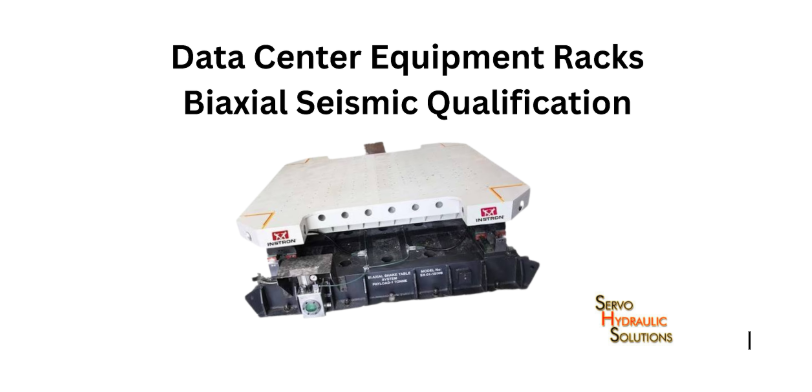
Data Center Equipment Racks Biaxial Seismic Qualification
What Is Data Centre Seismic Testing?
Data centre seismic testing is a controlled engineering evaluation that exposes equipment racks and their installed components to simulated earthquake motion. The objective is to determine whether the tested configuration can withstand the specified seismic demand without unacceptable structural damage or loss of required functionality.
The test may involve the entire rack, including populated cabinets, power equipment, cable connections, and anchorage hardware. The exact setup depends on the applicable qualification standard and the intended installation.
Why Server Racks Need Seismic Qualification
Server racks hold equipment that is often heavy, densely packed, and sensitive to movement. During an earthquake, the rack must resist lateral forces while supporting servers, switches, power distribution units, and other installed components.
Without appropriate seismic design, the rack may deform, anchor bolts may experience excessive forces, and mounted equipment may shift or become damaged. Cable connections can also be strained, potentially interrupting power or communications.
Consider a data center with several rows of fully populated server cabinets. Even if the building remains structurally sound, unsecured racks or damaged connections could interrupt critical services. Qualification helps engineers and facility operators evaluate these risks before equipment is installed.
Server Rack Biaxial Testing is particularly useful when the qualification programme needs to investigate the cabinet’s response to horizontal motion in two perpendicular directions.
What Happens to Racks During an Earthquake
Earthquake motion causes the floor supporting a rack to accelerate. Because the rack and its equipment have mass, they develop inertial forces that act through the frame, mounting rails, base, and anchorage.
Several responses may occur:
- The rack sways or bends under lateral loading.
- Equipment mass creates additional forces on mounting rails and structural connections.
- Anchor bolts and base plates experience tension, shear, or combined loading.
- Doors, panels, shelves, and internal components may move or loosen.
- Power cables and overhead connections may move relative to one another.
- Sensitive equipment may malfunction if vibration or movement exceeds its tolerance.
The outcome depends on the rack’s design, mass distribution, connections, anchorage, and the motion applied during testing. A cabinet with heavy equipment near its top may respond differently from an otherwise similar rack with a lower centre of gravity.
Seismic Load vs Static Equipment Load
Static equipment load describes the weight a rack supports under gravity. Seismic load refers to additional forces and responses caused by earthquake-induced acceleration.
These are related, but they are not interchangeable.
| Load type | What it represents | Why it matters |
|---|---|---|
| Static equipment load | Weight of servers, shelves, batteries, and other installed components | Checks the rack’s gravity-load capacity |
| Seismic load | Inertial forces generated by earthquake motion | Evaluates lateral strength, stability, and anchorage |
| Dynamic response | Movement and vibration of the rack and its components over time | Helps identify deformation, resonance, and potential damage |
| Cable load | Additional load representing specified overhead cable weight or cable-related forces | Helps reproduce the intended installation conditions |
A rack rated to support a particular equipment weight is not automatically qualified for earthquake loading. Seismic performance depends on the complete installation and the conditions used to evaluate it.
What Is a Biaxial Shake Table?
A biaxial shake table is a testing platform that can produce controlled motion along two perpendicular axes. It lets engineers evaluate how a specimen responds to horizontal excitation in two directions, rather than relying solely on a single-axis test.
For data-center equipment, engineers secure the rack to the table using the intended mounting arrangement, populate it with the specified test load, and instrument it to measure movement and response.
How Biaxial Seismic Testing Works
The testing process starts with a defined specimen configuration. Engineers install the rack, load it with representative equipment or approved substitute masses, secure the base, and connect the necessary monitoring instruments.
The shake table then applies the prescribed earthquake input. Depending on the test procedure, engineers may test the two horizontal directions sequentially or excite them simultaneously. These approaches are not identical, so the test method must match the applicable standard and qualification objective.
During testing, engineers may monitor:
- Table acceleration and the input motion.
- Rack acceleration at selected heights.
- Relative displacement between the rack top and base.
- Frame deformation and connection behavior.
- Anchorage movement or damage.
- Electrical or operational performance of installed equipment.
After the prescribed motion, the team inspects the rack, mounting hardware, and installed components. Functional checks determine whether the equipment still performs the required tasks.
When Biaxial Testing Is Suitable
Biaxial testing is appropriate when the applicable specification permits two horizontal axes, and the qualification objective focuses on horizontal earthquake response.
Typical applications include:
- Evaluating rack-frame stiffness and deformation.
- Assessing horizontal anchorage and base connections.
- Investigating the effect of equipment mass distribution.
- Comparing rack designs or mounting arrangements.
- Checking whether installed equipment remains functional after the specified motion.
For example, a manufacturer developing a new network cabinet may use biaxial testing to examine how the frame responds to motion along its front-to-back and side-to-side directions.
The decision should still be based on the required qualification procedure. A biaxial table’s ability to move in two directions does not, by itself, prove compliance with a particular standard.
Biaxial Testing vs Triaxial Testing
The main difference is the number of motion axes available during testing.
| Feature | Biaxial testing | Triaxial testing |
|---|---|---|
| Motion directions | Two axes, usually horizontal | Three axes, including vertical |
| Main evaluation | Horizontal seismic response | Horizontal and vertical seismic response |
| Typical focus | Rack stability, frame response, and anchorage | Additional effects associated with vertical acceleration |
| Equipment requirements | Two-axis motion capability | Three-axis motion capability and control |
| Qualification suitability | Depends on the applicable test procedure | Depends on the applicable test procedure and vertical-motion requirements |
Vertical acceleration can affect the forces acting on rack supports, equipment mounts, and internal components. Whether it must be included depends on the governing standard, test specification, and intended installation.
A three-axis test isn’t automatically required for every server rack, just as a two-axis test isn’t automatically sufficient for every qualification. The test plan must establish the required motion directions before equipment is selected.
Telcordia GR-63-CORE for Data Centre Racks
Telcordia GR-63-CORE is a technical requirements document associated with Network Equipment-Building System (NEBS) physical protection requirements for telecommunications equipment. It is widely referenced when evaluating the physical resilience of network equipment and supporting structures, including seismic performance.
For data center applications, the important question is whether the tested equipment, configuration, and results match the requirements of the intended installation. A general claim of seismic suitability is not a substitute for reviewing the applicable test evidence.
What NEBS Zone 4 Means
NEBS Zone 4 is a seismic qualification designation for telecommunications equipment that meets demanding earthquake test requirements under the applicable GR-63-CORE framework.
It is often used to evaluate racks and network equipment for installations with substantial seismic demands. However, the designation should be understood in the context of the relevant specification, issue, test method, and equipment configuration.
A Zone 4 claim does not mean a rack can survive every possible earthquake or that it suits every building. Actual performance depends on the tested configuration, the installation, and the seismic demands the equipment will experience.
When reviewing a manufacturer’s claim, request the test report and check the standard issue, equipment identification, installed mass, anchorage, and acceptance criteria.
GR-63-CORE Section 4.4 Earthquake Testing
Section references matter when reviewing qualification evidence. In commonly referenced editions of GR-63-CORE, Section 4.4 addresses earthquake-related requirements and performance criteria, while Section 5.4.1 details the earthquake test method. The applicable edition should always be checked before specifying or evaluating a test.
The earthquake-related requirements address both structural behaviour and equipment functionality. For example, the referenced requirements include limits on frame deflection and expectations for equipment operation before and after prescribed testing.
The precise criteria depend on the applicable issue and the equipment category. Engineers should not assume that a requirement from one edition applies unchanged to another.
For procurement or qualification, identify the exact document issue and clause in the test plan. This avoids confusion between the requirements an equipment product must meet and the procedure used to demonstrate compliance.
Required Test Configuration and Loading
The specimen should represent the equipment as it is intended to be installed. This may include the cabinet frame, shelves, installed or simulated equipment masses, base anchorage, and specified cable loading.
The test configuration should document:
- Rack dimensions, construction, and total mass.
- Equipment mass, individual shelf weights, and their vertical positions.
- Rack mounting arrangement and anchorage hardware.
- Any specified overhead cable load and how it is represented.
- Input motion, test sequence, and required response criteria.
- Functional checks and post-test inspection requirements.
Mass distribution matters. A rack loaded only near its base may behave differently from one carrying heavy equipment at higher levels. Similarly, a test using a different anchorage arrangement may not represent the actual installation.
The laboratory and equipment supplier should agree on the test configuration before testing begins.
Server Rack Biaxial Testing Requirements
Successful server rack biaxial testing requires more than placing a cabinet on a shake table. The rack structure, installed equipment, anchorage, cable loading, and acceptance criteria must be defined as one test system.
Rack Frame, Bracing, and Deflection Limits
The rack frame must withstand the prescribed motion without unacceptable deformation, instability, or damage to important connections. Engineers evaluate vertical members, cross-members, braces, mounting rails, doors, and other design-relevant structural elements.
Deflection is the amount a rack moves or bends relative to a reference point. Excessive movement can affect equipment clearances, cable connections, and structural stability.
The applicable test procedure may specify a frame-deflection limit. For example, GR-63-CORE Issue 3 requires that frame-level equipment’s maximum single-amplitude top deflection relative to its base does not exceed 75 mm (3 inches) during the specified earthquake waveform test. This value should not be treated as a universal limit for every rack standard or test configuration.
Equipment Load, Cable Load, and Anchorage
The test load should represent the intended installed configuration or the configuration explicitly required by the qualification procedure.
Distribute equipment mass appropriately across the rack’s height and mounting positions. Representative dummy loads may be used where live equipment is not necessary, provided they reproduce the relevant mass and arrangement.
Cable loading also needs attention. Some test plans specify a simulated overhead cable load to represent the additional weight associated with cable connections. The amount and method of application should follow the applicable requirements rather than an assumed standard value.
Anchorage must reproduce the intended installation as closely as the test method requires. Engineers should document bolt size, grade, spacing, base plates, and mounting conditions. A result obtained using a different base connection may not apply to the actual installation.
Structural and Functional Acceptance Criteria
Structural acceptance examines whether the rack maintains the required integrity during and after testing. This includes the frame, base, anchors, mounting rails, doors, and relevant connections.
Functional acceptance evaluates whether the equipment continues to perform its required tasks. Depending on the application, checks may include power continuity, network connectivity, alarms, equipment status, and recovery after the test.
These criteria should be defined before testing. For example, a network cabinet might remain structurally intact but temporarily lose connectivity. Whether that result is acceptable depends on the specified performance requirement.
The test report should distinguish between required performance before and after testing and any optional requirement for uninterrupted operation during the earthquake input.
Equipment That May Need Seismic Qualification
Seismic qualification may apply to more than the outer rack frame. Any equipment whose stability or operation is important to the installation should be assessed according to its role and applicable requirements.
Server Racks and Network Cabinets
Server racks and network cabinets support servers, storage systems, switches, and other electronic equipment. Qualification can evaluate frame integrity, anchorage, equipment retention, and how loaded cabinets behave under prescribed earthquake motion.
Open-frame racks and enclosed cabinets may respond differently because their structural arrangements, bracing, and panel connections differ. Results should be linked to the specific product and configuration tested.
Power Distribution Units and UPS Systems
Power distribution units (PDUs) supply electricity to equipment mounted within or connected to the rack. Uninterruptible power supply (UPS) systems may contain heavy batteries or other components that affect the centre of gravity.
Testing considerations include mounting strength, component retention, electrical connections, and how mass affects the supporting structure. Large standalone UPS units may require a separate qualification approach from rack-mounted power equipment.
Telecom Racks and Network Equipment
Telecommunications racks often contain switches, transmission equipment, routers, and other network components. Their qualification may need to demonstrate both physical integrity and continued service performance.
This is particularly important for infrastructure where a physical failure could interrupt communications. Equipment functionality criteria should reflect the service it provides and the relevant requirements.
Cable Trays and Overhead Support Systems
Cable trays, overhead supports, and connected cabling can affect the installation’s seismic behaviour. Their support systems must resist the loads and movements expected under the applicable design requirements.
A rack test that includes simulated cable loading does not automatically qualify the entire overhead cable tray system. The supports, building attachments, cable arrangement, and interfaces may need separate assessment.
Preparing a Rack for Shake Table Testing
Good preparation helps make a test representative and reduces the risk of delays or misleading results. Before the rack reaches the shake table, the test team should confirm the specimen configuration, mounting details, instrumentation, and acceptance criteria.
Define the Installed Equipment Configuration
Record the rack model, dimensions, total weight, equipment locations, shelf arrangement, and relevant accessories. Include the intended loading configuration and identify any differences between the test specimen and the production installation.
If dummy masses are used, their placement should represent the intended equipment distribution. Documenting these details makes it easier to determine which configurations the test results can reasonably support.
Select Anchorage and Mounting Hardware
Use the specified mounting arrangement and hardware. The test fixture must secure the rack to the table without introducing an unintended support condition that changes the response.
Record the anchorage details, installation procedure, and any required torque values. Inspect the connections before testing and document the mounting configuration with photographs or drawings.
The test setup should be reviewed to ensure that the table, fixture, and specimen can safely accommodate the required input motion.
Instrument the Rack and Monitor Performance
Instrumentation provides evidence of how the rack responds to the earthquake input. Accelerometers may measure motion at the table and selected rack locations, while displacement sensors can measure relative movement between the top and base.
Additional sensors may be used to investigate local deformation or connection response. If functionality is part of the acceptance criteria, use suitable monitoring equipment to record relevant electrical or network performance.
Before the test, verify sensor calibration, data channels, sampling settings, and system synchronisation. After each prescribed test stage, inspect the specimen and record any damage, loosening, or performance changes.
How to Review Seismic Qualification Evidence
A seismic qualification claim is useful only when the supporting evidence matches the equipment and intended installation. A test report should provide enough detail for engineers and procurement teams to understand what was tested and what the results establish.
What a GR-63-CORE Test Report Should Include
A useful report should identify:
- The applicable GR-63-CORE issue and test clauses.
- The laboratory and test date.
- The rack model, specimen configuration, and installed mass.
- Equipment distribution and any simulated cable load.
- Anchorage hardware and mounting arrangement.
- Shake table setup, input motion, and test directions.
- Instrumentation, recorded response, and relevant measurements.
- Structural inspection findings and functional test results.
- Deviations from the prescribed procedure and the final assessment.
A report that merely states “passed Zone 4” provides limited information if it does not identify the configuration and conditions behind the result.
Why “Zone 4 Tested” Is Not Enough
The phrase “Zone 4 tested” doesn’t explain the full scope of a qualification. It may leave important questions unanswered about the tested model, equipment weight, anchorage, test method, and acceptance criteria.
Two racks from the same product family may differ in height, frame design, or weight limits. Changes to mounting hardware or equipment distribution can also affect performance.
Review the report rather than relying only on marketing language. If the proposed installation differs from the tested specimen, ask the manufacturer or a qualified engineer whether the existing evidence applies or whether additional analysis or testing is necessary.
Matching Test Ratings to Installation Requirements
Qualification evidence should match the actual installation as closely as required by the governing specification. Compare the tested rack model, maximum supported equipment mass, loading distribution, anchorage, and required performance with the planned deployment.
Also consider the building’s seismic design requirements and any applicable project or regulatory standards. A product qualification is only one part of the installation’s overall seismic design.
Choosing Cost-Effective Seismic Testing
The most cost-effective testing programme is one that answers the required engineering questions without paying for unnecessary configurations or collecting data that cannot support the qualification decision.
Biaxial Table Specifications to Check
Before selecting a laboratory, review its ability to reproduce the required motion and safely accommodate the specimen.
Important specifications include:
- Table dimensions and payload capacity.
- Available displacement, velocity, and acceleration.
- Frequency range and control capability.
- Ability to reproduce the required waveform and response spectrum.
- Two-axis or three-axis motion capability, as needed.
- Fixture capacity and anchorage arrangements.
- Instrumentation, data acquisition, and functional monitoring.
- Experience with the applicable qualification standard.
A table’s maximum payload alone is not enough. The laboratory must be able to achieve the required motion with the actual specimen and fixture installed.
Fixtures, Sensors, and Data Acquisition
Fixtures must be strong enough to transfer the test forces while reproducing the intended mounting condition. Poor fixture design can distort results or create failure modes unrelated to the rack’s actual installation.
Sensors should be selected according to the measurements required by the test plan. Accelerometers, displacement transducers, and load measurement devices may all be useful, but the exact instrumentation depends on the procedure.
Confirm that the laboratory can provide traceable measurements, suitable calibration records, and a report that documents the test conditions and results.
Planning Tests for Multiple Rack Configurations
Manufacturers may want to qualify several rack heights, widths, loading arrangements, or mounting options. Testing every possible configuration may be expensive, but assuming that one specimen represents all variants can also be misleading.
A rational test plan identifies the most demanding configuration and explains why it represents the other proposed variants. Relevant factors include mass distribution, structural geometry, anchorage, bracing, and component placement.
Any extension of the test results to untested configurations should be supported by engineering justification and accepted under the applicable qualification requirements. This approach helps control costs without making unsupported claims about product performance.
Frequently Asked Questions
What is data center seismic testing?
It evaluates racks and related equipment under simulated earthquake motion to determine whether they meet specified structural and functional performance criteria.
Why do server racks need seismic qualification?
Qualification helps establish whether the rack, its anchorage, and its installed equipment can withstand the required seismic demand without unacceptable damage or loss of function.
What is a biaxial shake table?
A biaxial shake table generates controlled motion along two perpendicular axes, typically the two horizontal directions for rack testing.
Can a biaxial shake table test server racks?
Yes. It can test server racks when its capacity, motion capability, fixtures, and procedure meet the requirements of the intended qualification.
What is Telcordia GR-63-CORE testing?
It tests against applicable physical protection requirements for NEBS telecommunications equipment, including earthquake-related performance requirements.
What is NEBS Zone 4 seismic testing?
It refers to seismic qualification under the applicable NEBS requirements for Zone 4 conditions. The exact test procedure and acceptance criteria depend on the relevant specification issue.
What is GR-63-CORE Section 4.4?
In commonly referenced editions, Section 4.4 contains earthquake-related requirements and performance criteria. The detailed earthquake test method is addressed separately, commonly in Section 5.4.1. Always verify the applicable issue.
What is the difference between static and seismic load ratings?
A static rating describes capacity under specified stationary loads. A seismic qualification evaluates performance under prescribed earthquake motion, including dynamic response and anchorage behavior.
What is the difference between a seismic rack and a normal server rack?
A seismic rack is designed and, where required, tested against specified earthquake-performance criteria. A conventional rack’s equipment-weight rating alone does not demonstrate seismic qualification.
How is a server rack tested for earthquakes?
The rack is configured with representative equipment loads, secured to a shake table, instrumented, and subjected to the prescribed motion. Engineers then evaluate structural response and any required functional performance.
Does GR-63-CORE testing include vertical motion?
The required motion depends on the applicable edition, clause, and test procedure. Do not assume that a particular qualification includes or excludes vertical excitation without reviewing the test plan and report.
Is biaxial testing enough for GR-63-CORE Zone 4?
Not automatically. The test must comply with the applicable procedure, including its requirements for motion directions, waveform, specimen setup, and acceptance criteria.
What equipment load should be used during rack seismic testing?
Use the load specified by the applicable procedure or qualification plan, with a representative distribution of equipment mass. The report should state the tested load and arrangement.
What is a cable load in rack seismic testing?
It is an additional load used to represent overhead cables or related installation conditions when required by the test procedure. Its magnitude and application should be documented.
How are server racks anchored during seismic testing?
Racks are secured to the shake table using the specified mounting points and hardware to reproduce the intended installation. The fixture and anchorage must safely transfer the prescribed test forces.
What is rack deflection during an earthquake?
Rack deflection is the relative movement or bending of the frame under earthquake excitation. Excessive deflection may damage connections, affect equipment clearances, or compromise stability.
What is the difference between structural and functional seismic performance?
Structural performance concerns the rack’s strength, stability, deformation, and physical condition. Functional performance concerns whether the installed equipment continues to meet its required operating criteria.
What should a seismic test report include?
It should identify the standard and issue, specimen, equipment load, anchorage, test setup, input motion, instrumentation, results, inspection findings, functional checks, deviations, and assessment.
Does a Zone 4 rating apply to every rack configuration?
No. The rating applies within the scope supported by the qualification evidence. Different rack dimensions, equipment loads, or mounting arrangements may require additional engineering review or testing.
How much does server rack seismic testing cost?
The cost depends on the applicable standard, specimen size and weight, required motion, number of test configurations, instrumentation, laboratory time, and reporting requirements. An accurate estimate requires a defined test scope.
Conclusion
Data center seismic testing helps manufacturers and facility operators assess whether server racks and related equipment can withstand specified earthquake motion while meeting structural and operational requirements.
For a reliable Seismic Qualification Data Centre programme, define the intended equipment configuration, loading, anchorage, motion requirements, and acceptance criteria before testing. Review the complete test report rather than relying on a Zone 4 label alone.
When the test configuration matches the intended installation, and the evidence supports the required performance, seismic qualification provides a stronger basis for equipment selection, engineering review, and data center resilience.