- Have any Query
- (303) 807-1061
- doug@servohydraulicsolutions.com

Managing Cross Coupling & Pitch Interference in Shake Tables

Retrofitting Legacy Servo Hydraulic Actuators with Digital Controllers
November 5, 2026
Quasi-Static Cyclic Testing for Concrete & Steel Joints
November 7, 2026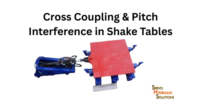
Multi-axis shake table control helps engineers reproduce the intended movement of a test platform while limiting unwanted motion between axes. Cross-coupling occurs when a command along one axis also produces movement or force along another, while pitch interference is unwanted rotational motion that can distort the test signal. Managing both necessitates coordinated actuators, accurate feedback, suitable mechanical alignment, and control strategies designed for the complete system.
In a multi-axis shake table the problem isn’t merely getting every actuator to move. Each actuator has to apply the correct force at the correct time without the others fighting it and without introducing any unwanted rotation.
That’s important in seismic testing. If a table is commanded to move horizontally and at the same time develops some unwanted pitching motion then the specimen is going to be subjected to an input that is different from what the engineer has actually intended. The way to deal with that is to find where the coupling is occurring and then deal with it via mechanical correction, control compensation, or both.
What is cross-coupling in multi-axis shake tables?
Cross coupling is when movement, force, or acceleration in one degree of freedom affects another. A horizontal movement command, for instance, may also result in a small amount of vertical acceleration or rotation.
There’s some interaction inherent in a multi-axis mechanism. The aim is to understand and control that interaction so that any unwanted motion stays inside acceptable test limits.
How cross-coupling occurs between horizontal, vertical, and rotational axes
A multi-axis shake table uses a number of actuators to control the movement of the platform. Depending on their individual design the actuators can provide both linear and rotational movement on all three axes (X, Y and Z).
The axes are mechanically linked via the platform, the actuator mounts, the joints and the supporting structure. The result is that a force applied in one direction can have an effect in another.
Common causes include:
- Actuators positioned at different angles or lever arms.
- Unequal actuator forces or response times.
- Flexible structures and associated mounting hardware.
- Payloads with an offset center of gravity.
- Hydraulic and control-system dynamics.
- Changes in specimen stiffness during testing.
For instance, a horizontal command may generate a small pitching moment if the force does not pass through the relevant center of rotation. Whether that effect becomes significant depends on the geometry, stiffness, payload, and control strategy.
Mechanical coupling vs. control coupling
Mechanical coupling comes from the physical system. It can result from actuator geometry, structural flexibility, mounting misalignment, friction, or the way forces travel through the platform.
Control coupling occurs when one control loop’s response influences another. The control system may not fully account for the platform’s dynamics, or one actuator’s correction may disturb another actuator’s movement.
| Type | Typical cause | Practical response |
|---|---|---|
| Mechanical coupling | Misalignment, flexible supports, eccentric payload | Inspect geometry, stiffness, joints, and load distribution |
| Hydraulic coupling | Pressure fluctuations, unequal flow, actuator dynamics | Check supply stability, valves, and hydraulic condition |
| Control coupling | Interacting control loops or an incomplete dynamic model | Identify system behavior and apply suitable decoupling. |
| Payload-induced coupling | Offset the center of gravity or change specimen stiffness. | Recalculate the loaded system and validate control settings. |
These sources can occur together. Increasing controller gain, for example, will not dependably fix a loose mount or an actuator that is mechanically misaligned.
Why cross-axis interference can worsen at higher frequencies
At higher frequencies, the system has less time to respond during each motion cycle. Actuator lag, hydraulic resonance, structural flexibility, and phase differences become more important.
A correction that works well at low frequency may not remain effective across the entire operating range. One actuator may respond slightly later than another, producing an unwanted rotational moment or cross-axis acceleration.
The effect depends on the table design and its usable bandwidth. Engineers should assess coupling across the intended combination of frequency, amplitude, payload, and acceleration rather than assuming that a single low-frequency calibration is sufficient.
How payload asymmetry and center-of-gravity offset amplify coupling
A specimen’s center of gravity influences how forces and moments act on the table. When the payload is unevenly distributed, a force that would produce mainly translation under a centred load may also generate rotation.
Consider a heavy equipment cabinet mounted closer to one edge of a platform. Horizontal acceleration can produce a moment because the mass is not distributed symmetrically around the platform’s relevant axes.
The result may be additional pitch or roll, different actuator loading, and increased interaction between axes. Correct payload measurement, mounting, and control configuration are therefore essential to mitigate dynamic cross-coupling.
What Is Pitch Interference in Shake Tables?
Pitch is rotation around a platform’s lateral axis, commonly described as rotation about the Y-axis when X represents forward motion and Z represents vertical motion. The exact axis convention depends on the machine’s coordinate system.
Pitch interference occurs when the platform develops unwanted pitch while executing another commanded motion, or when its pitch response differs from the intended test signal.
How pitch motion results from unequal actuator forces
In a multi-actuator system, the platform’s movement depends on the combined forces and positions of the actuators.
If actuators that ought to work together produce different forces, displacements, or timing, the resulting force distribution can create a rotational moment. Even a small difference can produce measurable pitch under certain payload and frequency conditions.
Possible causes include:
- Unequal actuator response or servo-valve behavior.
- Differences in actuator calibration.
- Incorrect geometry or mounting alignment.
- Payload eccentricity.
- Uneven hydraulic pressure or flow.
- Control parameters that do not account for cross-axis interaction.
First, determine whether the pitch originates in the mechanical arrangement, the hydraulic system, the controller, or the test specimen.
The relationship between pitch, roll, and yaw
Pitch, roll, and yaw describe rotation around three axes:
- Pitch: Rotation around the lateral axis.
- Roll: Rotation around the longitudinal axis.
- Yaw: Rotation around the vertical axis.
In a six-degree-of-freedom (6-DOF) system, these rotations are coordinated with translation along X, Y, and Z.
The rotational axes are not always independent in the physical system. Platform geometry, payload inertia, and actuator placement can cause a command on one rotational axis to affect the others. When evaluating rotational accuracy in 6-DOF shake tables, both hexapod and orthogonal layouts require careful attention to mechanical stiffness, payload balance, and coordinated control. The degree of interaction depends on the mechanism and the controller’s coordinate frame.
Why pitch interference distorts the intended waveform
Suppose a test calls for horizontal acceleration lacking significant pitch. If the platform pitches during the run, points on the specimen located away from the rotational center may experience additional acceleration.
The table’s measured translation may still look reasonable, while the specimen experiences a different motion because of the added rotation. This can affect the interpretation of structural response, especially when the specimen is tall, flexible, or mounted with a large offset from the rotation center.
How to distinguish pitch interference from genuine structural response
The specimen itself may flex or rotate under excitation. That response must not automatically be treated as a table-control error.
To distinguish the two, compare measurements from the table and specimen:
- Measure platform translation and rotation using appropriately placed sensors.
- Compare commanded motion with recorded table motion.
- Use specimen-mounted sensors to determine whether the observed rotation is local architectural response or platform movement.
- Check whether the pitch appears during an empty-table or reference test under strict controlled conditions.
- Repeat the test with the same configuration to establish whether the response is consistent.
Sensor location matters. An accelerometer positioned far from the rotation centre may register additional acceleration caused by rotation, even if its translational component is small.
How Cross-Coupling Affects Shake Table Test Accuracy
Cross coupling matters when unwanted motion becomes large enough to affect the test’s purpose. Its importance depends on the specimen, measurement requirements, frequency range, and test acceptance criteria.
Waveform distortion and motion accuracy
If a table is commanded to reproduce motion along one axis but responds along another, the actual input differs from the requested input.
This can affect displacement, velocity, acceleration, and phase. A table may track the main command reasonably well while still showing unwanted motion on a secondary axis.
Engineers should therefore evaluate both the commanded axis and the axes that are intended to remain quiet.
Impact on repeatability
Repeatability can suffer when coupling changes with payload position, hydraulic temperature, actuator condition, or specimen stiffness.
For example, a controller tuned with a centered rigid payload may behave differently after a flexible specimen is installed. The new load can change the system’s dynamic response, so previously effective control settings may no longer provide the same waveform accuracy.
When is cross-coupling a serious problem?
Cross coupling deserves closer attention when:
- Unwanted rotation exceeds the test’s allowable limits.
- Cross-axis acceleration affects the specimen’s expected loading.
- Actuators develop excessive internal or opposing forces.
- The measured waveform departs from the required test signal.
- Results differ greatly between equivalent runs.
- The system nears stability, force, stroke, or pressure limits.
A small amount of coupling is not automatically a failure. The key question is whether the measured interaction compromises the intended test or the equipment’s safe operating limits.
Multi-DOF Motion Simulation: Why Coupling Is Harder to Control
Multi-DOF motion simulation reproduces movement across several degrees of freedom at the same time. In seismic testing, this can more completely represent the motion structures and equipment experience.
The six degrees of freedom
A 6-DOF shake table can control three translational and three rotational motions:
| Degree of freedom | Motion | Example |
|---|---|---|
| X | Longitudinal translation | Forward and backward movement |
| Y | Lateral translation | Side-to-side movement |
| Z | Vertical translation | Up-and-down movement |
| Roll | Rotation about X | Side-to-side tilting |
| Pitch | Rotation about Y | Forward-and-backward tilting |
| Yaw | Rotation about Z | Turning around the vertical axis |
The ability to command six degrees of freedom does not mean that each axis operates independently. The actuators and platform form a coupled mechanical system, so motion in one direction can influence the others.
How actuators coordinate to produce a single-axis movement
A platform may need several actuators to move together to produce pure translation. Their required movements depend on the actuator geometry and the position of each connection point.
If the actuators do not follow their coordinated commands closely enough, the platform may develop unwanted rotation. Conversely, producing a pure rotation may require different actuators to extend or retract by carefully calculated amounts.
The controller must therefore translate the desired platform motion into appropriate actuator commands, accounting for the system’s geometry and dynamics.
1-DOF, 3-DOF, and 6-DOF systems
A 1-DOF table controls motion along one direction and generally presents a simpler control problem. A 3-DOF arrangement may control three translations and another defined combination of movements. A 6-DOF table adds three rotational motions and typically requires more complex coordination.
More degrees of freedom create additional interactions to identify and manage. The challenge isn’t that coupling increases in a fixed mathematical progression; it is that the number of interacting motions, actuators, and dynamic relationships grows with the system’s architecture.
Multi-Actuator Synchronization: The Foundation of Clean Motion
Multi-actuator synchronization means coordinating actuator movement and force so the platform follows its intended trajectory free of unacceptable differences in timing or response.
Why synchronization matters
If two actuators are supposed to contribute to the same movement but one lags, the platform may experience a momentary unwanted rotation. Synchronization is particularly important when the table carries a heavy specimen or reproduces a complex multi-axis signal.
How phase mismatch creates pitch and roll
Phase mismatch means two responses don’t reach corresponding points in their cycles at the same time. Even if their amplitudes are similar, a timing difference can create unequal instantaneous forces.
Depending on actuator placement, this disequilibrium may produce pitch, roll, or internal force in the mechanism.
The role of feedback sensors
Displacement transducers, accelerometers, and force sensors can help the controller determine how the system is actually moving. Their readings should be interpreted together because actuator displacement alone may not fully describe platform motion.
Sensor calibration, mounting position, signal quality, and sampling configuration all affect feedback accuracy.
Synchronization strategies
- Master–slave control: One actuator or reference signal guides the response of others. This can be simple but could fail to capture all interaction in a complex platform.
- Independent control loops: Each actuator has its own controller. This can work for simpler arrangements, but independently tuned loops may interact through the shared structure.
- Cross-coupled control: The controller uses information about differences between actuators or axes to coordinate their response.
- Model-based multi-axis control: A mathematical model maps desired platform motion into actuator commands and accounts for known dynamic relationships.
The suitable strategy depends on the table’s architecture, operating range, sensors, and control requirements.
Dynamic Cross-Coupling Mitigation Techniques
No single control method removes every type of cross-coupling. Engineers usually combine mechanical checks, system identification, feedback control, and compensation methods based on the interference source.
Decoupling control: separating motion axes mathematically
Decoupling control uses a mathematical model to reduce one axis’s influence on another. Instead of treating each actuator as isolated, the controller considers how the actuators collectively produce platform motion.
A common approach models the relationship between actuator movement and platform motion, then uses a transformation to calculate coordinated commands for the desired degrees of freedom.
For example, if a horizontal command tends to create pitch, the control strategy can compensate for the known relationship between horizontal actuation and rotational response. The effectiveness of this correction depends on the model’s quality and how closely the real system follows it.
Feedforward compensation
Feedforward control applies a calculated correction before the resulting error becomes significant. It is useful when the system’s behavior can be predicted from a dynamic model or from previously measured response data.
In a shake table, feedforward compensation may account for known actuator dynamics, inertia, or predictable cross-axis interaction. Feedback control then corrects the remaining difference between commanded and measured motion.
Feedforward is less effective when the underlying behavior changes substantially and the model is not updated. Payload changes, hydraulic variations, and structural flexibility should therefore be considered during configuration.
Adaptive and sliding-mode control
Adaptive control adjusts selected parameters as the system’s behavior changes. It may help when payload characteristics, hydraulic nonlinearities, or other operating conditions cause the system to depart from its original model.
Sliding-mode control is another approach used inside nonlinear systems. It is designed to preserve strong tracking despite certain uncertainties and disturbances. Pragmatic implementation must manage switching behavior, noise sensitivity, actuator limits, and stability.
These techniques are not automatic upgrades for every shake table. Their suitability depends on the system model, available measurements, computational platform, and validation requirements.
Model-based control and observer-based methods
Model-based control uses information about mass, stiffness, damping, geometry, and actuator dynamics used to calculate coordinated motion. It is particularly useful when the relationship between actuator forces and platform motion is too complex to tune each axis independently.
Observer-based methods estimate system states or disturbances from measured signals. If a disturbance cannot be measured directly, an observer can infer its effect and provide a controller correction.
Both approaches depend on appropriate models and trustworthy sensor data. A sophisticated algorithm is unable to reliably compensate for a major mechanical fault that has not been identified.
How Servo Valves and Hydraulic Dynamics Contribute to Cross-Coupling
Mechanical geometry is only part of the problem. Hydraulic actuators must receive the correct flow and pressure at the right time, and small differences between actuators can affect their coordinated response.
Unequal servo-valve response
Servo valves regulate hydraulic flow to control actuator motion. Differences in valve response, calibration, condition, or operating pressure can cause actuators to respond differently to nominally coordinated commands.
That difference may introduce a force imbalance and, depending on the actuator layout, unwanted pitch or roll.
Engineers should examine valve performance alongside actuator feedback, pressure, and measured platform motion rather than assuming that all cross-axis errors originate in the controller.
Hydraulic pressure fluctuations
Multiple actuators may share a hydraulic power unit. If pressure or available flow changes under a demanding load, actuator responses can be affected.
The result depends on the power unit’s capacity, accumulator arrangement, piping, valve demands, and the simultaneous requirements of the actuators.
Useful checks include supply pressure at dynamic load, fluid temperature, filtration, and whether the system retains the required flow during the most demanding portions of the test.
Oil-column resonance and high-frequency coupling
Hydraulic fluid and its lines have dynamic properties. Fluid compressibility, line length, hose flexibility, and system stiffness can create resonant behavior that influences actuator response.
When the test frequency approaches a relevant hydraulic or structural resonance, the response may show increased amplitude, phase changes, or unwanted interaction between axes.
The proper response is to identify the limiting dynamics as well as compare them with the required test profile. Simply increasing controller gain can reduce stability limits and worsen the problem.
The role of accumulators
Hydraulic accumulators can help support transient flow demand and reduce certain pressure fluctuations when properly sized and integrated. They are not a universal solution for cross-coupling.
Their effectiveness depends on pre-charge, capacity, location, pressure range, flow requirements, and the overall hydraulic circuit. An accumulator should be selected as part of the hydraulic system design, not added solely because an axis shows unwanted motion.
How Payload Characteristics Influence Cross Coupling
The specimen is part of the dynamic system, not just weight placed on top of the table. Its mass, center of gravity, stiffness, and mounting arrangement can change how the loaded platform responds.
Center-of-gravity offset
An offset center of gravity changes the moments produced by acceleration and actuator forces. The result can be increased pitch or roll, different actuator loads, and a change in the relationship between commanded movement and actual response.
Record the specimen’s mass and mounting position, and confirm that the table’s configuration accounts for the actual load.
Flexible vs. rigid payloads
A rigid payload mainly changes the mass and inertia the table sees. A flexible specimen can also introduce its own vibration modes, which may interact with the table’s motion.
For example, a tall structural frame may bend or sway under horizontal excitation. Accelerometers mounted at the top may record a combination of table input and structural response.
This is why sensor placement and data interpretation matter. The controller should reproduce the required table motion, while the test instrumentation measures the specimen’s response.
Mass distribution and coupling changes
Moving a heavy component from the center of the platform toward an edge changes the load allocation and rotational inertia. The same controller settings may then produce a different response.
Where the payload changes significantly between test campaigns, reassess the configuration and verify the system’s performance under the new loading condition.
Practical Example: Diagnosing Pitch Interference During a Shake Table Test
Imagine a laboratory running a horizontal seismic test on a heavy equipment assembly. The requested X-axis acceleration is tracked reasonably well, but sensors show unexpected pitch during the strongest portions of the input.
The useful first step is not to increase the pitch-control gain immediately. The team needs to determine whether the interference comes from actuator synchronization, the payload, hydraulic response, or mechanical alignment.
A practical diagnostic sequence is:
- Verify the measurements. Check sensor calibration, orientation, mounting, and signal quality.
- Compare commanded and measured motion. Review X-axis acceleration alongside pitch, roll, and the relevant actuator feedback signals.
- Inspect the payload. Confirm the mass distribution, centre-of-gravity position, mounting bolts, and fixture stiffness.
- Check actuator coordination. Look for timing differences, unequal displacement, or abnormal force distribution.
- Review hydraulic behavior. Check pressure stability, valve response, and any symptoms that appear under high dynamic demand.
- Inspect mechanical alignment. Look for binding, looseness, or geometry that could create an unwanted moment.
- Apply a targeted correction. Correct mechanical faults first, then revise control compensation where the remaining error is genuinely dynamic.
- Repeat and validate the test. Compare the corrected response alongside the original data using the same relevant test conditions.
This is an illustrative engineering scenario, not a report of a particular customer installation. Follow the equipment manufacturer’s procedures and the laboratory’s safety requirements for the exact diagnostic method.
How to Select a Shake Table System That Manages Cross Coupling
When evaluating a new system, look beyond the number of degrees of freedom. A table labelled 6-DOF does not automatically provide perfect axis separation.
Assess these areas before selecting equipment:
- Actuator layout: Ask how the geometry affects force distribution, rotational moments, and actuator travel.
- Control architecture: Confirm whether the controller supports coordinated multi-axis motion and suitable decoupling methods.
- Sensors: Review displacement and acceleration measurement range, resolution, bandwidth, calibration, and mounting arrangements.
- Hydraulic capacity: Check that the power unit can support simultaneous actuator demand within the intended operating envelope.
- Payload requirements: Provide realistic mass, center of gravity, stiffness, and mounting details.
- Test envelope: Specify the required frequency, displacement, velocity, acceleration, and combinations of simultaneous axes.
- Validation plan: Agree on how waveform accuracy, cross-axis motion, synchronization, and safety limits will be checked.
A useful supplier discussion should cover not just peak force or maximum frequency, but how the complete system behaves under the intended payload and multi-axis test profile.
Common Mistakes in Managing Cross-Coupling
Several avoidable mistakes can make cross-axis interference harder to diagnose.
- Assuming a 6-DOF table automatically decouples every axis. Six degrees of freedom describe the available motion, not the quality of its separation.
- Tuning actuators independently. Separate loops can interact through a shared platform, creating rotational errors.
- Ignoring payload changes. A new specimen or a changed mounting position can alter system dynamics.
- Increasing gain to hide mechanical problems. High gain cannot correct loose joints or incorrect alignment and may reduce stability limits.
- Checking only the commanded axis. Unwanted pitch or vertical acceleration may remain hidden unless you monitor secondary are.
- Skipping post-change verification. Any mechanical repair, sensor replacement, or controller adjustment should be followed by appropriate checks.
The general rule is simple: identify the source of the interference before deciding which correction to apply.
Recent Developments in Cross-Coupling Research
Research into multi-axis shake tables keeps focusing on better coordination, improved models, and control strategies that account for changing payloads and nonlinear hydraulic behavior.
A February 2026 study in Applied Sciences, titled “Redundantly Actuated Hydraulic Shaking Tables via Dual-Loop Fuzzy Control,” examined a control approach uniting platform-motion tracking with a force-coordination loop. Experiments on a 3 × 3 m six-degree-of-freedom table showed reduced waveform distortion and internal-force oscillation compared with the study’s single-loop baseline. These results apply to that setup and should not be treated as guaranteed for every table.
Another study, published in the Journal of Measurements in Engineering in February 2026, investigated adaptive integral sliding-mode control for attitude tracking in six-DOF electro-hydraulic shaking tables. It addressed parameter uncertainty, nonlinear effects, and cross-axis interaction, illustrating ongoing interest in controllers that respond to changing operating conditions.
Research published online in August 2026 also examined inversion-based iterative learning control for a two-degree-of-freedom electro-hydraulic shaking table, while other recent work has investigated frequency-domain iterative learning for random-vibration control. These approaches use measured response over repeated or analyzed motion cycles to improve tracking, but their suitability depends on the test signal, system dynamics, and stability requirements.
The practical takeaway is that modern Multi-Axis Shake Table Control is moving beyond treating each axis as a separate loop. Coordinated models, improved feedback, and adaptive compensation can help, but they must be supported by good mechanical design, reliable measurements, and testing under representative conditions.
Maintenance and Calibration Best Practices
Cross-coupling can change as equipment wears, sensors drift, and payloads vary. A maintenance plan should therefore track both component condition and the table’s dynamic performance.
- Calibrate displacement and acceleration sensors according to the required schedule and the manufacturer’s procedure.
- Inspect actuator alignment and mechanical joints for wear, looseness, and restricted movement.
- Monitor hydraulic performance for pressure instability, leakage, contamination, and changes in response.
- Record cross-axis behavior during suitable reference tests so changes can be identified over time.
- Document controller settings and any decoupling, filtering, or compensation parameters used for each payload.
- Revalidate after significant changes, including repairs, sensor replacement, control updates, or major specimen changes.
Maintaining a record of the test configuration is especially useful when a laboratory needs to compare results from different dates or specimen arrangements.
FAQs: Cross Coupling and Pitch Interference in Shake Tables
What is cross coupling in a shake table?
Cross coupling occurs when motion or force commanded along one axis affects another axis. It may result from mechanical geometry, hydraulic dynamics, payload characteristics, or interacting control loops.
What causes pitch interference in multi-axis shake tables?
Common causes include unequal actuator response, phase mismatch, actuator misalignment, an offset center of gravity, and control systems that do not adequately account for cross-axis interaction.
How do I reduce cross-axis interference?
Start by checking sensors, actuator alignment, payload geometry, and hydraulic behavior. Then assess whether coordinated control, decoupling, or feedforward compensation is appropriate for the remaining dynamic error.
What is multi-DOF motion simulation?
Multi-degree-of-freedom simulation reproduces motion across several translational and rotational axes. A six-DOF system can control X, Y, and Z translation plus roll, pitch, and yaw.
Why is actuator synchronization important?
Actuators must produce coordinated movements and forces to create the intended platform motion. Timing or response differences can introduce unwanted rotation, internal forces, and waveform error.
Can cross-coupling be eliminated?
In practice, the goal is usually to reduce coupling to an acceptable level rather than assume it can be eliminated under every load and frequency. Some interaction is inherent in the physical system, and its significance depends on the test requirements.
How does payload asymmetry affect accuracy?
An offset center of gravity changes the moments and forces acting on the platform. This can increase pitch or roll, change actuator loading, and require the control configuration to be reassessed.
When should I use decoupling control instead of mechanical correction?
Use mechanical correction when the cause is physical, such as misalignment, loose connections, or unsuitable mounting geometry. Use decoupling control for residual dynamic interaction that can be safely modelled and compensated. Some systems need both.
How can I tell whether my shake table has a coupling problem?
Look for repeatable unwanted motion on axes that should remain quiet, differences between commanded and measured waveforms, unexpected rotation, or changes in actuator force. Confirm the result with calibrated sensors and a controlled diagnostic test before changing the controller.
Conclusion
Managing cross-coupling and pitch interference is essential when a shake table must reproduce accurate multi-axis motion. Unwanted rotation can come from actuator timing differences, mechanical geometry, hydraulic behavior, payload asymmetry, or the interaction between control loops.
The most effective approach is to measure the problem, identify its source, and apply the right correction. Mechanical faults need mechanical solutions; dynamic relations may need coordinated control, decoupling, or compensation. After any change, test the system again under representative conditions.
Reliable multi-axis performance comes from treating the actuators, hydraulic supply, sensors, platform, payload, and controller as one connected system—not six independent axes.
Need Help Managing Cross-Coupling or Optimizing Multi-Axis Testing?
Whether you are designing a custom 6-DOF shake table, upgrading your control architecture, or resolving pitch interference and actuator synchronization issues, our engineering experts are ready to assist.