- Have any Query
- (303) 807-1061
- doug@servohydraulicsolutions.com
Energy Efficient Servo Hydraulics for Shake Table Testing Labs

Backlash-Free Swivels & Hydrostatic Bearings in Shake Tables
November 11, 2026
Earthquake Simulation Shake Table Cost & Pricing Factors: Teaching Platforms vs Custom Servo-Hydraulic Systems
November 12, 2026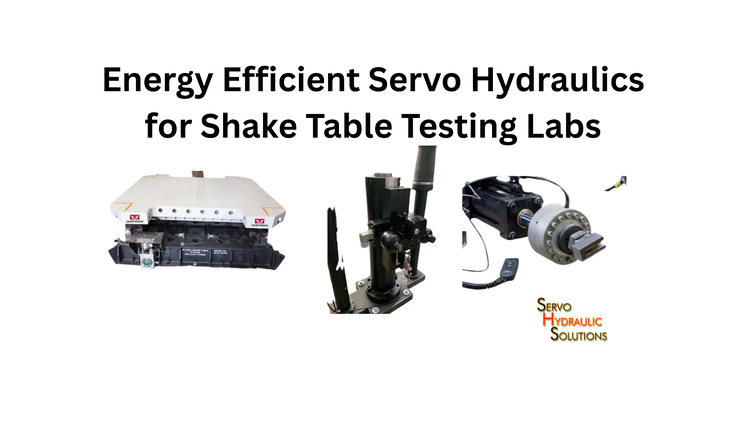
Energy-efficient servo hydraulics help shake table testing laboratories reduce electricity consumption without compromising the accuracy, speed, or reliability of structural tests. By combining variable-speed pumping, demand-based hydraulic control, efficient components, and energy monitoring, laboratories can reduce unnecessary power use while maintaining the high dynamic performance required for seismic simulation.
A shake table may operate at high force and speed during a test, but it does not need maximum hydraulic power every minute of the working day. The real opportunity is to match power generation with actual demand. This is where energy-efficient servo hydraulics, a properly designed VFD hydraulic power supply, and better system management can make a measurable difference.
Why Energy Efficiency Matters in Shake Table Labs
Shake table laboratories use hydraulic systems to produce controlled movements that simulate earthquake ground motion. Depending on the table size, payload, frequency range, and test requirements, the hydraulic equipment may need substantial flow and pressure.
The challenge is that the hydraulic power supply often operates for much longer than the actual high-demand testing period. Pumps may remain running during specimen installation, sensor checks, data preparation, and other activities. If the system continues producing more pressure or flow than required, electricity is consumed without contributing to useful table movement.
Improving efficiency is therefore not simply about installing a smaller motor. It involves examining how the entire hydraulic system operates.
Where Servo Hydraulic Systems Waste Energy
When calculating the long-term operational costs of continuous pumping versus intermittent testing, engineering teams also factor in evaluating total capital and operating costs of seismic systems before specifying new hardware.
Energy losses can occur at several points:
- Continuous pump operation: A fixed-speed pump may continue running even when the table is idle or requires very little hydraulic flow.
- Excess pressure: Maintaining pressure higher than the test requires increases the energy supplied to the hydraulic circuit.
- Relief-valve operation: When excess pump flow passes through a relief valve, much of its hydraulic energy is converted into heat.
- Flow restrictions: Undersized pipes, restrictive fittings, filters, and valves create pressure drops.
- Cooling demand: Hydraulic losses produce heat, which increases the workload of oil coolers and cooling-water systems.
- Poor maintenance: Contaminated oil, worn components, internal leakage, and incorrect settings can reduce system efficiency.
These losses may not be obvious during an individual test. However, when equipment operates across long laboratory shifts, even relatively small inefficiencies can add up.
Energy Use During Testing, Standby, and Cooling
A shake table’s energy demand changes throughout its operating cycle.
| Operating stage | Typical hydraulic demand | Energy-efficiency opportunity |
|---|---|---|
| Active testing | High or rapidly changing flow and pressure | Match pump output to dynamic demand |
| Specimen installation | Low or intermittent demand | Avoid unnecessary full-speed pumping |
| Sensor setup and calibration | Usually limited hydraulic movement | Use an appropriate low-demand mode |
| Standby | Little or no actuator movement | Reduce pump speed or use a suitable standby strategy |
| Cooling | Depends on heat generated by the system | Improve cooling control and reduce heat losses |
The active test may require full system capability, so reducing power during this stage must be approached carefully. Standby and preparation periods, however, often provide more straightforward opportunities for savings.
Benefits of Lower Power Consumption
A well-planned energy-efficiency programme can provide several benefits:
- Lower electricity consumption and operating costs.
- Less heat generation in the hydraulic circuit.
- Reduced cooling-system workload.
- Lower mechanical and thermal stress on selected components.
- Better control of pump operation across different test stages.
- Improved visibility into laboratory energy performance.
For a laboratory planning to expand its testing capacity, efficiency also matters because additional equipment does not always need to mean a proportional increase in power demand.
How Servo Hydraulic Shake Tables Use Energy
Understanding the hydraulic power path is the first step towards improving it. A typical servo hydraulic shake table system includes a hydraulic power supply, servo valves, actuators, sensors, control electronics, piping, and cooling equipment.
The power supply converts electrical energy into hydraulic energy. The control system then regulates the flow and pressure delivered to the actuators, which move the table according to the required test command.
Hydraulic Power Supply and Actuator Demand
The hydraulic power unit supplies pressurized oil to the actuators. The actuators convert that hydraulic energy into mechanical force and movement.
Their demand depends on several factors:
- Table mass and specimen weight.
- Required acceleration and displacement.
- Test frequency and waveform.
- Number and arrangement of actuators.
- Required force and velocity.
- Mechanical resistance and system losses.
A large specimen undergoing high-acceleration testing can require considerable hydraulic power. A smaller test or a low-demand preparation stage may need much less.
The power supply should be designed around the actual operating envelope, not simply the maximum theoretical demand. Oversizing every component to cover an occasional extreme condition can create unnecessary losses during normal operation.
Flow, Pressure, and Dynamic Test Requirements
Hydraulic power is related to pressure and flow. In practical units:
Hydraulic power (kW) = Pressure (bar) × Flow (L/min) ÷ 600
This relationship provides a useful estimate of hydraulic output power. Actual electrical input will be higher because pumps, motors, drives, and other components have efficiency losses.
Both pressure and flow matter. Pressure provides the force required by the actuator, while flow determines how quickly hydraulic fluid can move to produce actuator velocity.
Shake table testing creates a particular challenge because demand can change quickly. A system must respond to the commanded motion without introducing unacceptable delays, pressure fluctuations, or tracking errors.
Energy optimisation must therefore preserve the required dynamic response. Reducing pump speed too aggressively may save electricity but leave insufficient flow for the next part of the test.
Energy Losses in Valves, Piping, and Cooling
Hydraulic components are not perfectly efficient. Oil passing through a valve, pipe bend, filter, or fitting experiences resistance. This creates a pressure drop, and the energy associated with that drop is eventually converted into heat.
Servo valves are essential for accurate control, but pressure loss across a valve can be significant when high flow passes through it. Long or undersized hydraulic lines can add further resistance.
Heat is another important indicator. If the system repeatedly generates more heat than expected, it may be operating with unnecessary pressure losses, leakage, or inefficient control settings.
A practical energy review should measure pressure and flow at relevant points rather than assuming that the pump’s rated efficiency represents the efficiency of the complete installation.
VFD Hydraulic Power Supply for Shake Tables
A VFD hydraulic power supply regulates the speed of the electric motor coupled to a hydraulic pump through a variable frequency drive. Instead of operating continuously at one fixed speed, the motor can adjust its speed to suit the required hydraulic output.
For a shake table laboratory, this can help reduce unnecessary pumping during low-demand periods. However, the VFD must be selected and integrated around the pump type, hydraulic circuit, control response, and test requirements.
What Is a VFD Hydraulic Power Supply?
A variable frequency drive changes the frequency and voltage supplied to an AC motor, allowing the motor’s rotational speed to be controlled.
When connected to a suitable hydraulic pump, the VFD can regulate pump output by changing motor speed. A lower pump speed generally produces lower flow, provided the pump is operating within its specified range.
The system may use feedback from pressure, flow, or other operating measurements to determine the required motor speed.
A VFD does not replace the servo control system responsible for accurate table motion. Instead, it manages the electric motor and pump that provide hydraulic power to the system.
How VFD Pump Control Reduces Energy Use
In a conventional fixed-speed arrangement, the pump may continue delivering substantial flow even when the actuators need very little. Excess flow may be bypassed or returned through a pressure-control arrangement, wasting energy.
A correctly designed VFD arrangement can reduce pump speed when demand falls. This reduces the amount of hydraulic energy being generated unnecessarily.
The potential benefit is greatest when the system has meaningful periods of variable demand. It may be less attractive when the pump must operate close to full output for almost the entire test schedule.
The U.S. Department of Energy identifies adjustable-speed pumping as an energy-management opportunity and provides guidance on matching pump operation to system requirements. Its resources also emphasize that pump-system efficiency depends on the complete installation, not just the drive.
Reference: https://www.energy.gov/cmei/ito/pump-systems
Matching Pump Speed to Actuator Demand
The pump must supply enough flow to meet the actuator’s requirements while maintaining the pressure needed for the test.
A demand-based arrangement can use measured system conditions to adjust motor speed. For example:
- During standby, the control system identifies that actuator flow demand is low.
- The pump speed is reduced to an approved standby level.
- Before a test begins, the system prepares for the required flow and pressure.
- During active testing, pump output follows the defined operating requirements.
- After the test, the system returns to an appropriate low-demand condition.
The transition between these states needs careful engineering. The system must be ready to deliver the required hydraulic output before the table begins its commanded motion.
VFD Control During Standby and Low-Flow Periods
Standby operation is one of the most useful areas to examine when planning a VFD hydraulic power supply.
A laboratory may have long periods when the table is not moving, but the hydraulic system remains available. Instead of maintaining full pump speed throughout, the system can use a defined standby mode where technically suitable.
Possible strategies include:
- Reducing pump speed while maintaining the required minimum pressure.
- Using a suitable pressure-control arrangement.
- Switching off selected pumps when they are not required.
- Separating standby supply from high-demand test supply.
- Coordinating pump operation with the laboratory’s test schedule.
The correct approach depends on the hydraulic architecture. Some systems need continuous circulation, cooling, or pressure availability. Others can operate with reduced output or controlled shutdown—and for existing shared units, multi-station legacy HPU retrofits with VFD controls can pair speed modulation with slow-ramp manifolds and station interlocks. The equipment manufacturer’s limits and the test system’s safety requirements should guide the decision.
Smart Hydraulic Distribution for Testing Labs
Energy efficiency is not determined by the pump room alone. Hydraulic oil must travel from the power supply to the actuators, and the distribution arrangement affects pressure loss, response, maintenance, and operating cost.
A well-designed distribution system supplies the required flow without creating unnecessary restrictions or keeping unused equipment pressurised.
Centralized Pump Room vs Local Power Units
A centralized pump room can serve multiple test stations. This arrangement may reduce equipment duplication and allow the laboratory to manage pump capacity according to combined demand.
However, a centralized system also needs careful planning. Long hydraulic lines can increase pressure losses, and simultaneous tests may create high peak-flow requirements.
Local power units place hydraulic equipment closer to individual test stations. This can reduce distribution distance and allow independent operation, but multiple units may increase maintenance requirements and installed equipment capacity.
| Design factor | Centralized pump room | Local power units |
| Equipment arrangement | Shared hydraulic supply | Separate supplies near test stations |
| Space requirement | Dedicated pump-room space | Space near each test station |
| Distribution | May require longer pipe runs | Usually shorter local connections |
| Operating flexibility | Shared capacity management | Independent station control |
| Expansion | Depends on spare system capacity | Additional units can be added locally |
Neither arrangement is automatically more efficient. The decision should consider the laboratory’s test schedule, distance between stations, required flow, maintenance access, and future expansion plans.
Hydraulic Ring Main and Service Manifolds
A hydraulic ring main can distribute pressurized oil around a laboratory, allowing test stations to connect through suitable service manifolds.
The arrangement can provide flexibility when several test areas share a common supply. Properly designed isolation valves also make it easier to service individual stations without affecting the entire installation.
The design should consider pipe diameter, flow velocity, pressure drop, return-line capacity, filtration, and the possibility of simultaneous testing.
A ring main should not be treated as an energy-saving feature by itself. Its benefit depends on correct sizing and how the connected equipment is operated.
Reducing Pressure Losses in Piping
Hydraulic piping should be sized for the required flow and operating conditions. Undersized pipes can lead to an excessive drop in pressure, whereas unneeded bends and restrictive fittings increase flow resistance.
Useful design checks include:
- Review pipe diameter against maximum and normal flow.
- Avoid unnecessary sharp bends and sudden changes in pipe size.
- Select suitable low-loss fittings and valves.
- Keep filters clean and monitor pressure drop across them.
- Check return lines for restrictions and excessive back pressure.
- Use suitable pipe routing to simplify inspection and maintenance.
A small pressure loss may seem unimportant at one connection. Across a complete hydraulic network, however, several restrictions can contribute to avoidable energy consumption.
Isolating Unused Test Stations
When several stations share a hydraulic supply, unused connections should not create unnecessary demand.
Suitable isolation arrangements can allow operators to disconnect or deactivate stations that are not required. This helps the supply system serve the active test areas instead of maintaining unnecessary flow through idle circuits.
Isolation must be designed so that it does not interfere with pressure relief, safe unloading, or other protective functions.
Energy-Saving Hydraulic Components
Selecting efficient components can improve system performance, but the components must work together. A high-efficiency pump will not deliver the expected benefit if the system operates at excessive pressure or loses energy through poor control.
Variable Displacement Pumps
A variable displacement pump can change the volume of oil delivered per revolution. This allows the pump to adjust output without relying only on motor-speed changes.
Depending on the design, displacement control can reduce flow when demand is low while maintaining the motor at a suitable operating speed.
Variable displacement pumps may be useful where pressure and flow requirements change across the testing cycle. Their selection should consider response time, control stability, efficiency across the operating range, and compatibility with the servo hydraulic circuit.
Accumulators for Transient Flow Demand
Hydraulic accumulators retain energy by holding fluid under pressure. They can supply additional flow during short periods of high demand and help manage pressure fluctuations.
For a shake table, an accumulator arrangement may support transient flow requirements when properly integrated into the hydraulic supply.
However, accumulators do not create free energy. They must first be charged, and losses occur during charging and discharge. Their size, pre-charge pressure, operating pressure range, and connection arrangement must be selected for the actual duty cycle.
An accumulator should be considered as part of a complete hydraulic design, not added simply because a system experiences high peak demand.
Low-Friction Actuators and Efficient Servo Valves
Actuators, seals, bearings, and servo valves all influence hydraulic efficiency.
Internal leakage, friction, unsuitable clearances, and worn sealing surfaces can increase the power required to produce the same mechanical output. Selecting components that match the load and operating range helps reduce these losses.
Servo valves must also be selected for the required flow capacity and dynamic response. An oversized valve may not provide the best control characteristics, while an undersized valve may restrict flow and affect performance.
The objective is not to choose the component with the lowest quoted pressure drop in isolation. It is to achieve the required force, velocity, accuracy, and stability with the least practical energy loss.
Efficient Cooling and Heat Management
Hydraulic cooling systems remove heat generated by pumps, valves, leakage, and other losses.
If the hydraulic system produces unnecessary heat, the cooling equipment must work harder. Reducing pressure losses and avoiding continuous high-pressure operation can therefore reduce both hydraulic and cooling energy use.
Cooling capacity should match actual heat load. Temperature sensors, controlled fans, suitable heat exchangers, and properly maintained cooling circuits can help avoid unnecessary operation.
Oil temperature must remain within the equipment manufacturer’s specified range. Reducing cooling energy should never mean allowing the oil to overheat.
Reducing Energy Use During Shake Table Testing
Energy-saving measures must work with the test programme. A shake table needs accurate motion control, and energy reduction should never come at the expense of the required earthquake simulation.
Match Hydraulic Supply to Test Phases
Not every stage of a test requires the same hydraulic output.
A practical laboratory can define operating modes for preparation, standby, test readiness, active testing, and post-test shutdown. Each mode can have appropriate pressure, flow, and pump-speed settings.
For example, a table may need only limited hydraulic support during specimen installation. During a high-amplitude seismic test, it may require much higher flow and pressure.
The control strategy should make these transitions predictable. Operators should also be able to confirm that the system has reached the required operating condition before starting a test.
Reduce Unnecessary Relief-Valve Losses
Relief valves protect hydraulic systems against excessive pressure. They are important safety components, but continuous operation across a relief valve can waste energy.
If a pump supplies more flow than the system requires, the excess may pass through the relief arrangement and generate heat.
A review should check whether the pressure setting is appropriate, whether the pump is oversized, and whether the control system is maintaining unnecessary pressure.
Relief valves must never be disabled or adjusted outside approved limits to improve efficiency. Energy-saving changes should preserve all required pressure-protection functions.
Manage Peak Demand and Regenerative Energy
Shake table systems may experience high hydraulic demand during rapid changes in acceleration or direction. Managing this peak demand can help avoid oversizing the entire power supply for conditions that occur only briefly.
Possible design approaches include suitable accumulator capacity, coordinated pump operation, and a hydraulic supply designed around measured demand profiles.
Some systems may also investigate regenerative energy recovery. During deceleration or when a load drives an actuator, energy may be available for recovery depending on the hydraulic and electrical architecture.
Recovery is not automatic. It requires compatible equipment, suitable control logic, and a clear assessment of where the recovered energy can be used or stored. The engineering design must also account for the test’s dynamic response and safety requirements.
Optimise Test Sequences and Table Motion Profiles
Test planning can influence energy use. Repeated unnecessary movements, long idle periods with the power supply operating at full capacity, and poorly coordinated test sequences can increase consumption.
Where test objectives allow, laboratories can organize preparation and testing activities to reduce avoidable operating time.
However, the prescribed earthquake record, displacement history, frequency content, and loading sequence must remain unchanged when they are essential to the research or qualification requirement.
The aim is to improve the efficiency of the supporting hydraulic system, not alter the test conditions to make the equipment consume less power.
Sustainable Structural Testing Lab Design
A Sustainable Structural Testing Lab considers energy consumption as part of its overall design and operating strategy. Hydraulic equipment, electrical infrastructure, cooling, ventilation, and test scheduling should be considered together.
Energy Monitoring and Power Metering
Energy monitoring helps laboratories understand where electricity is being used and when unnecessary consumption occurs.
Useful measurements include:
- Total electrical energy consumed by the hydraulic power unit.
- Motor power and operating hours.
- Pump speed during testing and standby.
- Hydraulic pressure and flow.
- Oil temperature and cooling-system operation.
- Energy consumption for individual test cycles, where practical.
Comparing energy use across similar tests can reveal changes caused by operating settings, equipment condition, or test duration.
It is also useful to separate hydraulic power consumption from other laboratory loads. Otherwise, improvements in one system may be hidden by unrelated electricity use.
Pump Room Ventilation and Heat Management
Pump rooms need adequate ventilation and temperature management. Electric motors, hydraulic equipment, and cooling systems can release significant heat during operation.
Poor ventilation can increase room temperature and place additional demands on cooling equipment. A planned ventilation system helps maintain suitable operating conditions and supports equipment reliability.
The layout should also provide enough space for maintenance, oil handling, filtration, and safe access to electrical and hydraulic components.
Preventive Maintenance for Hydraulic Efficiency
Maintenance has a direct effect on energy use. A system that develops internal leakage or operates with contaminated oil may need more power to deliver the same performance.
A practical maintenance programme should include:
- Checking for external and internal leakage.
- Monitoring oil cleanliness and filter condition.
- Inspecting pump and motor performance.
- Checking valve operation and pressure settings.
- Monitoring abnormal temperature increases.
- Inspecting hoses, fittings, and pipe connections.
- Reviewing cooling-system performance.
Maintenance records can help identify gradual deterioration. If a power unit begins consuming more energy for a comparable test, the change may indicate a developing hydraulic or mechanical issue.
Planning for Future Lab Expansion
A laboratory’s hydraulic demand may change as new shake tables, larger specimens, or additional test stations are introduced.
Planning for expansion at the design stage can prevent the need to replace an otherwise suitable power system. Engineers should consider future peak flow, pressure requirements, simultaneous testing, spare connections, and pump-room capacity.
Modular power units or a properly planned centralized supply may provide flexibility. The best choice depends on the laboratory’s expected workload and the performance requirements of each test station.
When expanding laboratory capabilities or addressing ageing equipment, combining energy-efficiency upgrades with retrofitting legacy servo-hydraulic systems or upgrading your testing equipment can significantly extend machine life while reducing overall operating costs.
How to Implement Energy-Efficient Servo Hydraulics
Energy improvements should begin with measurements, not assumptions. A VFD or a new pump may be useful, but the laboratory first needs to understand its current hydraulic demand.
Audit Current Hydraulic Energy Use
Start by reviewing the existing power supply and its operating patterns.
Record electrical consumption during active testing, standby, preparation, and shutdown. Where possible, measure hydraulic pressure and flow at the same time.
Look for signs of avoidable energy use, such as continuous high pump speed during idle periods, frequent relief-valve operation, excessive oil temperature, or large pressure drops across the distribution network.
This audit provides a baseline for comparing improvements later.
Define Test Demand and Duty Cycles
The next step is to understand what the shake table actually requires.
Review the test programme and identify:
- Maximum and normal operating pressure.
- Required flow during different test conditions.
- Peak actuator velocity and force.
- Typical test duration.
- Time spent in standby and preparation.
- Frequency of simultaneous test operations.
A duty-cycle profile is particularly useful. It shows how long the system operates at different demand levels and helps determine whether variable-speed control is likely to provide a worthwhile benefit.
Select and Commission VFD Controls
Once demand is understood, engineers can evaluate a suitable VFD and motor arrangement.
The selection should consider motor ratings, pump characteristics, operating speed range, cooling, electrical compatibility, control response, and protection requirements.
Commissioning should include controlled checks of:
- Motor rotation and drive configuration.
- Pump operation across the approved speed range.
- Pressure and flow response.
- Standby and low-demand transitions.
- Temperature and vibration.
- Emergency shutdown and protective functions.
- Servo system response during representative test conditions.
The VFD should be integrated with the hydraulic and test-control architecture by qualified engineers. It should not introduce instability or delay when the shake table needs to respond to a commanded motion.
Verify Performance Without Compromising Test Quality
After commissioning, compare the updated system with the original energy baseline.
Use comparable test conditions wherever possible. Record electrical energy, hydraulic pressure, flow, pump speed, oil temperature, and table tracking performance.
The key question is not simply whether electricity consumption has fallen. The system must also maintain the required displacement, acceleration, frequency response, force capacity, and repeatability.
A 2026 study published in Energy Engineering examined a closed-loop electrohydraulic system using VFD and programmable logic controller-based pump-speed control. The researchers reported a 20.6% reduction in rated electrical power consumption under the studied operating condition. This is a useful example of current research into demand-based electrohydraulic control, but the reported result should not be treated as a guaranteed saving for shake table installations. Actual performance depends on the system design and duty cycle.
Frequently Asked Questions
1. How can shake table testing labs reduce energy consumption?
Laboratories can reduce energy use by matching pump output to actual actuator demand, using suitable variable-speed controls, reducing unnecessary pressure losses, improving hydraulic distribution, and maintaining equipment properly. Monitoring energy during testing and standby helps identify where improvements will have the greatest effect.
2. What is energy-efficient servo hydraulics?
Energy-efficient servo hydraulics refers to hydraulic systems designed to provide accurate force and motion control while minimising unnecessary electrical and hydraulic losses. It combines suitable pumps, motors, valves, actuators, controls, and cooling arrangements.
3. What is a VFD hydraulic power supply?
A VFD hydraulic power unit controls the rotational speed of the electric motor driving a hydraulic pump by utilizing a variable frequency drive. This allows pump output to change with system demand instead of remaining at a fixed speed.
4. Can VFDs be used with hydraulic pumps?
Yes. VFDs can be used with compatible motor and pump arrangements to regulate pump speed. However, engineers must check the pump’s operating limits, motor compatibility, minimum speed, cooling requirements, and the hydraulic system’s pressure and flow needs.
5. Can hydraulic energy be recovered during shake table testing?
Energy recovery may be possible when an actuator or moving load returns energy to the hydraulic or electrical system. Accumulators and suitable regenerative arrangements can help capture or reuse some of this energy, depending on the system design. Recovery must be evaluated carefully to maintain safe and accurate table operation.
Conclusion
Energy-efficient servo hydraulics can help shake table laboratories reduce operating costs, manage heat, and make better use of their installed power capacity. The most effective improvements usually come from treating the hydraulic system as a complete unit rather than focusing on a single pump or component.
A suitable VFD hydraulic power supply, efficient pump selection, well-designed piping, appropriate accumulators, and demand-based operating modes can all contribute to lower energy consumption. The first step is to measure existing performance and understand the laboratory’s actual test requirements.
Most importantly, energy savings must be verified without compromising test accuracy, dynamic response, or safety. When hydraulic supply, control strategy, maintenance, and monitoring work together, laboratories can move towards more sustainable structural testing while retaining the performance their research and qualification programmes demand.
Looking to Optimize Your Laboratory’s Hydraulic Efficiency?
Discuss your custom VFD power supply upgrades, energy audits, or shake table hydraulic requirements with our engineering team today.