- Have any Query
- (303) 807-1061
- doug@servohydraulicsolutions.com

Pit-Mounted vs Free-Standing Buttress Shake Tables: Facility Cost, Access & Foundation Comparison Guide

Large Hydraulic Shaker Table Procurement Guide: Sizing Overturning Moment, Reaction Mass & Actuator Force
November 12, 2026
Modernizing Legacy Instron 8500 & 1341 Servohydraulic Load Frames: Electronics, Valve & Software Upgrade Guide
November 18, 2026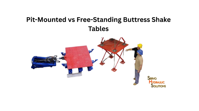
Earthquake simulation shake table prices range from 653–3,000 for small open-source educational stepper platforms and 15,000–45,000 for entry-level commercial units, while custom high-payload servo-hydraulic shake tables typically require custom engineering quotes starting from tens of thousands to several hundred thousand dollars depending on payload, axes (uniaxial vs. multi-DOF), and Hydraulic Power Supply (HPU) capacity. Choosing an open-architecture COTS servo-hydraulic system allows university and commercial labs to match real seismic velocity and force requirements without paying proprietary OEM markups.
A pit-mounted shake table and a free-standing buttress shake table can both support demanding earthquake simulation, but they require different laboratory layouts and installation approaches. A pit-mounted system places much of its mechanism below floor level, while a buttress arrangement uses an above-floor reaction structure to support the actuators. The better choice depends on specimen size, crane access, foundation conditions, available space, and the cost of preparing the facility.
For a laboratory planning a new structural testing facility, this decision should be made early. Changing the layout after construction can mean expensive civil modifications, restricted access, and difficult equipment installation.
What Is a Pit-Mounted Shake Table?
A pit-mounted shake table is installed in a recessed foundation below the surrounding laboratory floor. The moving platform is positioned at or near floor level, while supporting components such as actuators, bearings, and parts of the reaction structure are located inside the pit.
This arrangement is useful when laboratories need to test large specimens without placing the entire table assembly above floor level. It can also make specimen loading and movement around the platform easier, provided the pit and surrounding facility are designed correctly.
How a Pit-Mounted Shake Table Works
A pit-mounted system uses hydraulic actuators to move a platform through controlled vibration or seismic motion. The actuators are connected between the moving table and a supporting reaction structure integrated with the foundation.
A typical system includes:
- A moving platform for mounting the specimen.
- Hydraulic actuators that generate the required motion.
- Bearings or guidance systems to support controlled movement.
- A reaction structure and reinforced foundation.
- A hydraulic power unit (HPU), servo valves, and piping.
- Sensors and a digital controller for closed-loop motion control.
During operation, the controller sends commands to the servo valves. Pressurized hydraulic fluid drives the actuators, moving the platform according to the required test profile. Feedback sensors measure the actual movement so the controller can correct differences between the commanded and measured response.
The recessed installation keeps much of the mechanism below the working floor. This can help when handling large specimens, although the pit must still provide enough space for inspection, servicing, and safe access.
Where Actuators and Bearings Are Located
In a typical pit-mounted arrangement, the actuators are installed below or around the moving platform, depending on the table’s axis configuration and mechanical design.
Bearings and guidance components support the platform and help control unwanted movement. Their location depends on the required motion, load capacity, and table architecture.
Keeping these components below floor level can reduce above-floor obstructions. However, it also means maintenance access must be planned carefully. Engineers need enough clearance to inspect actuator connections, hydraulic lines, bearings, sensors, and other equipment without dismantling major sections of the installation.
Confirm the final arrangement through equipment layout drawings before pit construction begins.
You can study more about servo-hydraulic testing machines and strong floor frames.
When a Pit-Mounted Shake Table Is Suitable
A pit-mounted shake table is worth considering when:
- Large specimens need to be positioned close to floor level.
- Overhead crane access is important.
- The laboratory is being designed as a new facility.
- A recessed installation suits the required testing arrangement.
- The project can accommodate excavation and substantial foundation work.
- The actuator and bearing assemblies can be accessed safely below floor level.
For example, a laboratory testing tall structural frames may benefit from a floor-level platform because specimens can be moved into position without negotiating a large raised machine structure. The benefit depends on the actual specimen dimensions and crane arrangement, not simply the presence of a pit.
What Is a Free-Standing Buttress Shake Table?
A free-standing buttress shake table uses a substantial above-floor support structure to resist the forces generated during testing. The actuators connect the moving platform to this reaction structure, which transfers loads into the foundation.
Unlike a pit-mounted arrangement, the main supporting structure is visible and accessible above the laboratory floor. This can simplify certain installation and maintenance tasks, particularly in facilities where deep excavation is difficult or impractical.
How a Buttress Shake Table Works
A buttress system uses hydraulic actuators to drive the moving platform. The actuators react against a strong support structure, commonly made from reinforced concrete or a suitably engineered structural assembly.
When an actuator pushes the table in one direction, the buttress resists the opposing force. The buttress and its foundation must resist these forces while maintaining the stiffness and alignment required for accurate testing.
The complete installation generally includes:
- A moving shake table platform.
- Hydraulic actuators and associated connections.
- A buttress or reaction structure.
- A reinforced foundation and anchorage system.
- Hydraulic power and control equipment.
- Sensors, safety systems, and mounting fixtures.
The buttress is not simply a support wall. Its geometry, stiffness, anchorage, and foundation connection must be designed around the actuator forces and expected dynamic loads.
Where Actuators and Reaction Structures Are Located
In a free-standing buttress arrangement, the reaction structure sits above the floor and is usually beside or around the moving platform.
Actuators are installed between the buttress and the moving assembly. Their orientation depends on whether the system is designed for uniaxial, biaxial, or more complex motion.
The above-floor layout can make some components easier to inspect. Technicians may have direct access to actuator mounting points, hydraulic connections, and structural interfaces.
However, the buttress occupies laboratory space and can affect crane movement, specimen positioning, and access around the table. These issues should be checked using a full-scale facility layout before the equipment is ordered.
When a Free-Standing Buttress Shake Table Is Suitable
A free-standing buttress shake table may be a practical choice when:
- Deep excavation is restricted by existing foundations or underground services.
- The laboratory already has a suitable strong floor.
- The project needs an above-floor reaction structure.
- Maintenance access to the actuators is a priority.
- The facility has enough space for the buttress and specimen handling.
- A new pit would create major construction or drainage complications.
For an existing university laboratory, a buttress arrangement may be easier to integrate than excavating a large pit. That doesn’t automatically make it cheaper: the strong floor, anchorage, and reaction structure still need to meet the system’s design loads.
Pit-Mounted vs Buttress Earthquake Simulator
The main difference between a pit-mounted and buttress earthquake simulator is how the reaction structure and supporting components are arranged within the facility.
A pit-mounted design places much of the mechanism below floor level. A buttress design uses a visible above-floor reaction structure. Both can be engineered for demanding seismic testing, but their construction, access, and space requirements differ.
| Comparison | Pit-mounted shake table | Free-standing buttress shake table |
| Main arrangement | Recessed below floor level | Above-floor reaction structure |
| Excavation | Usually required | May be avoided or reduced |
| Reaction structure | Often integrated with pit foundation | Typically visible beside or around platform |
| Floor-level access | Platform can be near floor level | Depends on platform height |
| Crane access | Can be favourable with suitable clearance | Buttress may restrict some crane movements |
| Maintenance | Requires planned pit access | Some components may be easier to reach |
| Retrofit suitability | Can be difficult in existing buildings | May suit some existing facilities |
| Space requirement | Uses below-floor space | Uses above-floor laboratory space |
Installation and Civil Works Comparison
Pit-mounted installations normally require excavation, reinforced concrete construction, waterproofing where needed, drainage provisions, embedded components, and careful dimensional control.
These activities must be coordinated with the shake table design. If the pit dimensions or embedded anchor positions are incorrect, installation can become complicated.
A buttress installation avoids the need for a deep equipment pit in many configurations, but it still requires a foundation that can resist substantial forces and moments. The reaction structure may also require large concrete sections and reinforcement.
The cost difference depends on site conditions. Excavating a pit in difficult ground can be expensive, while constructing a large buttress and strengthening an existing floor can also require major civil work.
Specimen Access and Crane Clearance
Specimen handling is often one of the most important practical differences.
A pit-mounted platform can provide a relatively unobstructed working area around the table. This may help when moving large specimens from a staging area onto the platform.
A buttress structure can create restrictions depending on its height, width, and position. It may limit the crane’s approach or reduce the space available for lifting and rotating specimens.
The crane must be assessed for more than its rated lifting capacity. Check hook height, lifting radius, runway position, headroom, and the complete path from the loading area to the table.
Reaction Wall and Strong Floor Layout
A pit-mounted system may use a reaction structure integrated into the recessed foundation. A buttress system typically places its reaction structure above floor level and transfers loads through its foundation.
Both arrangements require a clear understanding of the load path.
The structural design should identify:
- Actuator locations and directions of applied force.
- Reaction loads and overturning effects.
- Foundation stiffness and anchorage.
- Connections between the reaction structure and foundation.
- Interaction with nearby strong floors and reaction walls.
A strong floor alone does not guarantee that a shake table can be installed without modification. Its thickness, reinforcement, stiffness, embedded anchorage, and load capacity must be checked against the proposed equipment.
Laboratory Space and Retrofit Constraints
A pit-mounted design uses space below the floor but needs excavation and construction access. Installation may be difficult in an operating laboratory with existing underground services or nearby foundations.
A buttress design uses more visible floor space. It can be considered for retrofit projects where excavation is not feasible, provided the existing structure can support the required loads or can be strengthened.
Before selecting either layout, map the complete facility. Include the table, buttress or pit, hydraulic equipment, control room, specimen storage, crane route, maintenance areas, and emergency access.
Maintenance and Operational Access
A pit-mounted system needs safe access to below-floor components. Depending on the design, this may involve access ladders or stairs, removable covers, lighting, ventilation, drainage, and designated lifting points for maintenance.
A buttress system can make some actuator and reaction-structure components easier to inspect from floor level. However, access may still be restricted around the back of the structure or between actuators.
In both cases, plan for routine inspection, hydraulic hose replacement, bearing maintenance, sensor calibration, and removal of heavy components. Maintenance access should be part of the initial design, not an issue left until commissioning.
Shake Table Foundation and Reaction Wall Layout
The foundation and reaction wall layout determine how forces from the shake table are transferred into the laboratory structure and ground. This is a critical part of a structural lab shake table installation guide because poor coordination can affect performance, safety, and long-term maintenance.
Reaction Mass and Foundation Requirements
The foundation must resist the forces and moments generated during operation while limiting unwanted movement.
Depending on the configuration, the system may use a large reinforced concrete reaction block, an integrated pit foundation, a buttress foundation, or a combination of structural elements.
The design should consider:
- Maximum actuator forces and their directions.
- Dynamic and overturning loads.
- Specimen mass and centre of gravity.
- Foundation stiffness and allowable movement.
- Concrete strength and reinforcement.
- Anchor bolts and embedded plates.
- Ground conditions and nearby structures.
No universal foundation size or reaction-mass ratio applies to every shake table. These values must be determined from the equipment loads, site investigation, and structural engineering analysis.
Pit Depth, Walls, and Drainage
For a pit-mounted table, pit depth must provide the clearance required for actuators, bearings, connections, and moving components throughout their operating range.
The design should also allow enough space for inspection and repair. A pit that fits the equipment but leaves no room for technicians is not a good installation.
Pit walls and base slabs must be designed for the applicable structural and environmental loads. Drainage and waterproofing are also important, especially where groundwater, washdown water, or hydraulic fluid leakage could create problems.
Consider:
- Water ingress and groundwater conditions.
- Drainage channels and sump arrangements, where appropriate.
- Safe access and lighting.
- Removable covers and guarding.
- Ventilation and inspection clearance.
- Protection of electrical and hydraulic connections.
Drainage should be designed so that water cannot accumulate around sensitive equipment or create a safety hazard.
Reaction Wall Position and Loading Direction
The reaction wall or buttress must be positioned to match the actuator arrangement and intended directions of motion.
Its location affects actuator geometry, load transfer, available specimen space, and maintenance access. A poorly positioned reaction structure can also create awkward hydraulic routing or interfere with crane operations.
The equipment supplier should provide reaction-load information and interface drawings early enough for the structural engineer to verify the layout.
Hydraulic Piping and Utility Routing
Hydraulic pipes and hoses must connect the HPU to the actuators without interfering with moving components or creating access hazards.
The layout should provide suitable space for:
- Pressure and return lines.
- Drain and cooling connections.
- Electrical power and control cables.
- Sensor and feedback wiring.
- Cable trays and protective conduits.
- Isolation and maintenance points.
Keep hydraulic lines protected from impact and excessive bending. Flexible connections may be needed near moving components, but their routing and service life should be considered during design.
Strong Floor Integration
If the shake table is installed near an existing strong floor or reaction wall, assess how the new foundation interacts with the existing structure.
Check whether the new installation needs independent foundations, structural connections, isolation joints, or modifications to existing reinforcement and anchorage.
Do not assume that an existing strong floor can accept the new equipment simply because it was designed for structural testing. The actual load cases and dynamic response must be reviewed.
Facility Cost Comparison
The total facility cost includes more than the shake table itself. Civil works, utilities, installation, crane access, and future maintenance can make a significant difference between pit-mounted and buttress layouts.
Civil and Foundation Costs
A pit-mounted arrangement generally adds excavation and below-floor construction to the project. A buttress arrangement may reduce excavation but require a substantial above-floor reaction structure and supporting foundation.
The more practical option depends on the site. For a new laboratory, a pit may be incorporated into the original building design. For an existing facility, the cost of excavation, relocation of underground services, or strengthening nearby structures may make a buttress layout more attractive.
Excavation, Concrete, and Reinforcement Costs
Pit construction may involve soil removal, shoring, groundwater management, waterproofing, concrete walls, and a reinforced base slab.
A buttress layout may require large concrete sections, reinforcement cages, anchor assemblies, and local strengthening of the strong floor.
Request a separate civil-work estimate for each layout. This makes it easier to compare equipment installation costs rather than relying on a single combined quotation.
Hydraulic and Electrical Infrastructure Costs
Both configurations need hydraulic and electrical services. These may include the HPU, cooling system, power supply, hydraulic piping, control cables, grounding, and safety circuits.
The location of the HPU matters. A long distance between the power unit and the actuators can affect piping design, pressure losses, service access, and installation cost.
Installation, Commissioning, and Training Costs
The quotation should clarify whether installation, alignment, hydraulic flushing, calibration, commissioning, operator training, and performance verification are included.
Also confirm who is responsible for civil-interface checks, lifting equipment, transport inside the facility, and final acceptance testing.
Long-Term Operating and Maintenance Costs
Compare the cost of routine hydraulic servicing, filter and seal replacement, cooling-system maintenance, sensor calibration, and spare parts.
A pit-mounted installation may need additional access arrangements for servicing below-floor equipment. A buttress may provide easier access to certain components but can require more working space around the structure.
The lowest initial installation cost is not necessarily the lowest long-term cost.
Specimen Access and Crane Requirements
A shake table can meet every technical requirement and still be inconvenient to use if specimens are difficult to move onto it. Crane and handling arrangements should therefore be included in the facility design.
Overhead Crane Height and Load Capacity
Check the crane’s rated capacity against the heaviest specimen, lifting fixture, and rigging arrangement. Also verify hook height, headroom, lifting radius, and runway coverage.
A tall specimen may need additional clearance during lifting and rotation. The crane must be able to position it safely without contacting the buttress, roof structure, hydraulic lines, or other equipment.
Specimen Positioning and Assembly Space
Allow space for specimen assembly, instrumentation, mounting, and removal. Large test articles may need to be assembled beside the table before being lifted into position.
Consider the complete movement path, not only the final position above the platform.
Pit Access for Large or Deep Specimens
For a pit-mounted system, consider whether the specimen can be lowered or positioned without interfering with the pit edges and covers.
The design should also provide safe access for technicians who need to work around the platform or inspect components below floor level.
Safety, Maintenance, and Emergency Access
Maintain clear access to emergency stops, electrical isolation points, hydraulic isolation valves, and escape routes.
Pit covers, guardrails, ladders, lighting, and safe lifting arrangements should be included where required by the facility risk assessment and applicable safety rules.
Which Shake Table Layout Fits Your Laboratory?
The best layout depends on whether the project is a new facility or a retrofit, how specimens will be handled, and what civil work the site can accommodate.
Choose Pit-Mounted for Large Specimens and Deep Testing
A pit-mounted layout may be preferable when:
- The laboratory is being designed from the ground up.
- A near-floor-level platform is important.
- Large specimens need clear crane access.
- The facility can accommodate excavation and drainage.
- The below-floor mechanism can be serviced safely.
It can provide a practical working arrangement for large structural specimens, provided the pit is designed around the complete equipment and maintenance requirements.
Choose Buttress for Existing Labs and Faster Installation
A free-standing buttress shake table may suit facilities where deep excavation is difficult or where the existing building layout favours an above-floor reaction structure.
It can be a practical retrofit option, but the existing floor and foundation must be checked. The buttress also needs enough space for the specimen, crane, hydraulic connections, and maintenance access.
When a Hybrid Layout Is the Better Option
Some laboratories may benefit from a combination of recessed and above-floor features. For example, part of the equipment may be installed below floor level while selected reaction components remain accessible above the floor.
A hybrid layout is not automatically simpler or cheaper. It should be considered when it solves a specific access, space, or structural constraint that neither standard arrangement addresses effectively.
Questions to Ask Before Selecting a Layout
Before approving the design, ask:
- What are the maximum specimen dimensions, mass, and centre-of-gravity height?
- What actuator forces and reaction loads must the foundation resist?
- Is excavation practical, and are underground services present?
- Can the overhead crane reach the table safely?
- Is there enough space for specimen assembly and maintenance?
- Where will the HPU, cooling system, and control equipment be located?
- What access and drainage provisions are needed?
- What are the full civil, installation, and lifecycle costs?
Frequently Asked Questions
What Is a Pit-Mounted Shake Table?
A pit-mounted shake table is installed in a recessed foundation, with the moving platform generally positioned near floor level. Depending on the design, its actuators, bearings, and supporting components may be located partly or fully below the surrounding floor.
What Is a Free-Standing Buttress Shake Table?
A free-standing buttress shake table uses an above-floor reaction structure to support the actuators and resist the forces generated during testing. The structure transfers these loads into a suitably designed foundation.
What Is the Difference Between Pit-Mounted and Buttress Shake Tables?
A pit-mounted system places much of its mechanism below floor level, while a buttress system uses an above-floor reaction structure. Pit-mounted designs involve excavation and below-floor access planning; buttress designs use more laboratory floor space and need suitable structural support.
Which Shake Table Layout Costs More to Install?
Neither layout is always more expensive. A pit-mounted system may cost more where excavation, groundwater control, and waterproofing are difficult. A buttress system may cost more where a large reaction structure or major floor strengthening is needed. Site conditions and equipment requirements determine the final cost.
Does a Pit-Mounted Shake Table Need a Reaction Mass?
Yes. A pit-mounted system still needs a suitable reaction structure and foundation to resist actuator forces. Integrating the equipment below floor level does not remove the need for adequate structural support.
Does a Buttress Shake Table Need a Reaction Wall?
Yes, it needs an appropriately designed reaction structure, commonly a buttress or reaction wall. Its dimensions, stiffness, anchorage, and foundation must suit the actuator forces and dynamic loads expected during testing.
Conclusion
Choosing between a pit-mounted and free-standing buttress shake table is as much a facility-planning decision as an equipment decision. Pit-mounted layouts can provide useful floor-level access for large specimens. At the same time, buttress systems may suit laboratories where excavation is difficult or an above-floor reaction structure is more practical.
Before finalizing the layout, compare the full foundation and civil-work requirements, crane access, specimen handling, hydraulic routing, maintenance needs, and lifecycle costs. Involve the shake table supplier and structural engineer early so the facility is designed around the actual equipment and testing programme.
Need Help Planning Your Shake Table Layout & Foundation?
Whether you are designing a new facility with a pit-mounted system or retrofitting an existing lab with a buttress shake table, our engineering team can help you size actuators, reaction masses, and COTS servo-hydraulic configurations.