- Have any Query
- (303) 807-1061
- doug@servohydraulicsolutions.com
Analog-to-Digital Servo Valve Amplifier & Signal Conditioner Retrofits: Wiring, LVDT & Feedback Compatibility

Modernizing Legacy Instron 8500 & 1341 Servohydraulic Load Frames: Electronics, Valve & Software Upgrade Guide
November 18, 2026
Multi-Degree-of-Freedom (6-DOF) Hexapod vs Orthogonal Actuator
November 19, 2026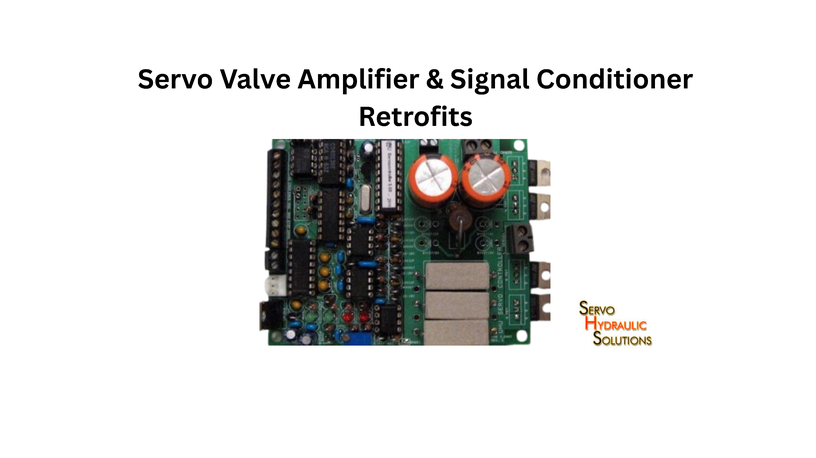
A servo valve amplifier and signal conditioner retrofit can modernise an ageing hydraulic test stand without replacing the entire machine. The key is to make the new digital electronics work correctly with the existing servo valves, LVDT feedback, sensors, wiring and safety circuits while preserving reliable control and measurement performance.
Many older hydraulic testing systems still use analogue valve drivers and LVDT signal conditioners. These components may continue to function, but finding replacements, maintaining calibration and integrating them with modern controllers can become difficult. A carefully planned servo valve amplifier retrofit offers a practical route to better diagnostics, easier configuration and improved long-term support.
The challenge is that an amplifier is not simply a plug-in replacement. Its input signals, output characteristics, feedback scaling and electrical connections must match the existing system. A mismatch can affect actuator movement, measurement accuracy or closed-loop stability.
Why Upgrade Hydraulic System Software?
Hydraulic test stands depend on several connected elements: control software, digital or analogue electronics, servo valves, feedback transducers and data acquisition hardware. Upgrading one part without checking the others can create unexpected compatibility problems.
A software upgrade may be sufficient for some machines. Others need new valve drivers, signal conditioners or a complete controller replacement.
Common Problems With Legacy Windows XP Test Controllers
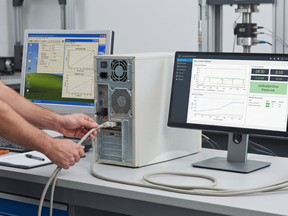
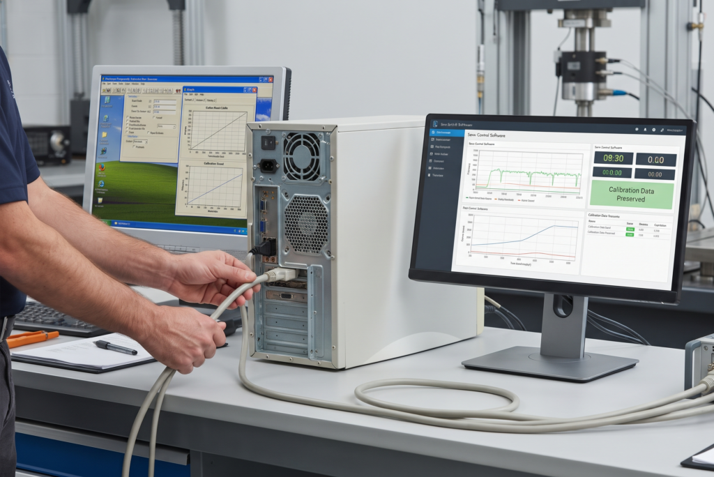
Older test controllers may use Windows XP-based computers because the original control application and hardware drivers were designed around that environment.
Common problems include:
- Hardware failure: Ageing computers, storage drives and interface cards can become unreliable.
- Limited replacement options: Finding compatible legacy cards and components may be difficult.
- Driver incompatibility: Older interface hardware may not have drivers for current operating systems.
- Software limitations: Existing applications may not support modern data formats or communication methods.
- Maintenance difficulties: Technicians may need specialist knowledge to maintain an ageing configuration.
- Cybersecurity exposure: Windows XP no longer receives routine security updates from Microsoft.
Replacing the computer alone does not solve every problem. If the original application depends on a specific interface card or driver, the complete control chain must be checked before migration.
Risks of Continuing With Obsolete Software
An old operating system does not automatically make a test stand unsafe or inaccurate. The concern is the increasing difficulty of maintaining the complete system.
A failed hard drive, unavailable driver or damaged interface card can interrupt testing. If the original installation media and configuration files are missing, restoring the system may take considerably longer.
There is also a risk of losing access to historical test programs, calibration records and measurement data. These records should be backed up before any upgrade begins.
For machines connected to a laboratory network, an unsupported operating system can create additional security concerns. Keeping a legacy computer isolated may reduce exposure, but it does not remove the need for a long-term migration plan.
Benefits of a Modern Software Upgrade
A well-planned hydraulic system software upgrade can provide:
- Compatibility with supported modern computers and operating systems.
- Better data storage, export and reporting options.
- Improved system diagnostics and fault monitoring.
- Easier backup and recovery procedures.
- Better integration with modern data acquisition equipment.
- More accessible software maintenance and technical support.
- A clearer path for future hardware upgrades.
The benefits depend on the scope of the project. A software update cannot improve the mechanical condition of an actuator or compensate for a worn servo valve.
When a Software-Only Upgrade Is Enough
A software-only upgrade may work when the existing controller hardware remains reliable and supported by the replacement application.
It is worth considering when:
- Existing interface cards have compatible modern drivers.
- Valve amplifier electronics are functioning correctly.
- Sensor signal conditioning remains accurate and stable.
- Safety circuits can remain unchanged and independently verified.
- The replacement software supports the existing control architecture.
If the original hardware depends on discontinued cards or unsupported communication interfaces, a software-only approach may not be practical.
Migrating Legacy Windows XP Test Controller Software
Moving an older test controller to Windows 10 or Windows 11 involves more than installing a new operating system. The application, interface hardware, communication protocols and control functions must all be checked.
How Legacy Windows XP Test Controllers Work
A typical legacy test controller includes a computer running the test application, an interface connecting the computer to control electronics, and a feedback system that monitors actuator movement or applied force.
The control software sends commands to the controller hardware. The hardware processes these commands and drives the servo valve amplifier. Feedback signals from LVDTs, load cells and other transducers return to the control system.
This creates a closed-loop arrangement:
- The operator enters a test command.
- The controller processes the command.
- The valve driver supplies the required electrical signal to the servo valve.
- Hydraulic flow moves the actuator.
- Feedback sensors measure the response.
- The controller compares the measured response with the command and adjusts the output.
If any part of this chain is incompatible with the new software environment, the machine may not operate as intended.
What Can Be Migrated From a Legacy System?
Depending on the original application and file formats, several items may be transferable:
- Test procedures and program files.
- Test reports and measurement records.
- User-defined test sequences.
- Channel names and measurement configurations.
- Control parameters and documented operating settings.
- Calibration certificates and historical records.
- Alarm descriptions and maintenance documentation.
These items should be checked individually. A file that opens successfully in a new application is not necessarily ready for use in a live control system.
What Cannot Be Directly Migrated?
Some legacy components depend on hardware or software that cannot be transferred directly.
Examples include:
- Drivers written for Windows XP.
- Proprietary interface-card software.
- Unsupported communication protocols.
- Hardware-specific control applications.
- Old configuration utilities that require discontinued libraries.
- Software tied to a particular computer or hardware licence.
A replacement application may need to recreate the original configuration rather than import it.
Control parameters should never be copied blindly. Their meaning, units, scaling and relationship with the hardware must be confirmed.
Windows XP to Windows 10/11 Migration Steps
A structured migration reduces the chance of losing important information or disrupting machine operation.
Step 1: Create a complete backup
Back up the operating system image where possible, application installers, licence information, configuration files, test programs and historical records.
Keep a separate copy of the original system so the previous setup can be referenced during migration.
Step 2: Identify hardware dependencies
Record the computer interface cards, communication ports, input/output modules, controller models and connected electronics.
Check whether supported drivers are available for the intended operating system.
Step 3: Review the existing application
Identify which functions are essential, including test sequencing, closed-loop control, data recording, alarms and reporting.
Do not assume that every feature of the old application will behave identically in a replacement.
Step 4: Select the migration approach
There are three common options:
- Retain the existing controller hardware and install compatible software.
- Replace the computer and interface hardware while retaining suitable control electronics.
- Replace the complete controller when the old architecture cannot be supported.
Step 5: Rebuild and verify the configuration
Confirm channel assignments, engineering units, sensor scaling, control settings and alarm limits.
Step 6: Commission before production testing
Begin with safe, controlled checks. Verify feedback direction, valve response, emergency stops, limits and data recording before conducting full test sequences.
Windows 10 and Windows 11 should not be treated as interchangeable targets. Hardware and software compatibility must be confirmed for the exact version selected.
Common Migration Challenges and Solutions
| Challenge | Practical approach |
| No modern driver for an interface card | Replace the card or use a supported interface |
| Old software will not install | Rebuild the application environment or select a replacement |
| Missing configuration files | Recover settings from backups and original documentation |
| Different channel scaling | Recalculate and verify scaling against known inputs |
| Communication problems | Confirm protocol, cabling, addressing and interface compatibility |
| Unexpected control response | Review control configuration and recommission under controlled conditions |
When a Full Controller Replacement Is Needed
A full controller replacement becomes more sensible when the original hardware is unsupported, unreliable or incompatible with the required software.
It may also be necessary when the system needs more control channels, faster data acquisition, modern communication interfaces or improved diagnostics.
The decision should be based on the complete system architecture, not simply the age of the computer.
Modern Data Acquisition for Old Shake Tables
A modern data acquisition system can improve the way an older shake table records and analyses test responses. It can provide better channel management, synchronised measurements and easier data export, provided the existing sensors and signal-conditioning hardware are compatible.
How Modern DAQ Improves Old Shake Tables
A modern DAQ system can collect measurements from multiple sensors and organise them into a common test record.
Depending on the hardware, it may support:
- Higher channel counts.
- Better synchronisation between measurement channels.
- Configurable sampling rates.
- Improved data storage and export.
- Real-time signal monitoring.
- Easier integration with analysis software.
For example, a shake table test may require simultaneous recording of table displacement, acceleration, actuator position and specimen response. A suitable DAQ system can organise these signals so engineers can compare the table input with the specimen’s measured behaviour.
The required sampling rate, resolution and channel count depend on the test frequency range and measurement objectives.
What Sensors Can Be Retained During a DAQ Upgrade?
Existing sensors may be retained if their electrical characteristics and condition are suitable.
Potentially reusable devices include:
- LVDTs.
- Accelerometers.
- Load cells.
- Pressure transducers.
- Strain-gauge sensors.
- Other analogue measurement transducers.
Before reuse, check the sensor’s output type, excitation requirements, signal range, wiring, connector arrangement and calibration status.
A sensor that produces a valid signal is not automatically compatible with a new DAQ input.
What Sensors Usually Need Replacement?
Replacement may be necessary when sensors are damaged, unstable, obsolete or unsuitable for the required measurement range.
Common reasons include:
- Excessive electrical noise.
- Intermittent output.
- Damaged cables or connectors.
- Unavailable excitation or signal-conditioning hardware.
- Insufficient measurement range or resolution.
- Poor calibration history.
In some cases, the sensor itself is serviceable, but its old signal conditioner is not. Replacing the conditioner may be enough.
Matching DAQ Channels to Test Requirements
The DAQ specification should come from the measurements required, rather than the number of channels available in the existing system.
Consider the following:
| Requirement | What to check |
| Channel count | Number of sensors and future expansion needs |
| Input type | Voltage, current, bridge, IEPE or other required inputs |
| Sampling rate | Highest relevant signal frequency and analysis requirements |
| Resolution | Ability to distinguish the smallest meaningful measurement |
| Synchronisation | Timing alignment across channels |
| Signal conditioning | Excitation, filtering, amplification and isolation |
| Data storage | File format, duration and export requirements |
For dynamic shake table testing, channel synchronisation is particularly important. Measurements that are not time-aligned can lead to incorrect comparisons between table motion and specimen response.
Integrating Modern DAQ With Legacy Controllers
A new DAQ system can sometimes operate alongside an older controller.
For example, the existing controller may continue handling actuator control while the new DAQ records additional specimen accelerations and structural responses.
However, the two systems need a reliable timing reference if their data must be compared. Trigger signals, clock synchronisation and signal scaling should be checked.
The DAQ should not be allowed to interfere with the control loop or safety functions.
When a Full DAQ Replacement Is Needed
A complete DAQ replacement may be appropriate when the old system has insufficient channels, unreliable measurements, unsupported hardware or no practical way to integrate additional sensors.
It is also worth considering when the laboratory needs synchronised multi-channel acquisition, modern data formats or a more maintainable measurement architecture.
Open-Architecture Servo Control Software
Open-architecture servo control software gives laboratories more flexibility in selecting and integrating control hardware. It can reduce dependence on a single proprietary platform, but the system still needs careful engineering and validation.
What Is Open-Architecture Servo Control Software?
Open-architecture software is designed around accessible interfaces and documented integration methods rather than being restricted to one manufacturer’s complete hardware and software package.
Depending on the design, it may work with commercially available controllers, input/output modules, data acquisition devices and servo amplifier hardware.
This does not mean every component can be connected to every other component. Electrical interfaces, communication protocols, timing and control behaviour must still match.
Benefits of Open-Architecture Systems
Potential benefits include:
- More choice when sourcing replacement components.
- Easier integration with selected third-party hardware.
- Greater flexibility for future upgrades.
- Better access to configuration and diagnostic information.
- Reduced dependence on proprietary service arrangements.
- More control over data formats and system interfaces.
For a laboratory maintaining several generations of hydraulic test equipment, this flexibility can be valuable.
Limitations of Open-Architecture Systems
Open architecture also places more responsibility on the system integrator.
The laboratory or retrofit supplier must confirm that the selected components work together. This includes signal conditioning, valve drive, feedback processing, communication and safety functions.
A flexible platform may also require more configuration and commissioning than a complete proprietary package.
When Open-Architecture Software Is Suitable
It may be suitable when:
- The laboratory wants to retain serviceable legacy hardware.
- Replacement components are available from multiple suppliers.
- The control requirements are clearly documented.
- The laboratory has access to suitable integration expertise.
- Future expansion and long-term maintainability are priorities.
When a Proprietary System Is Better
A proprietary system may be the better option when a complete, supported control package is required and the manufacturer can provide verified compatibility, commissioning and ongoing service.
It can also be suitable when the test stand depends on specialised control functions that would be difficult to recreate using separate components.
How to Avoid Vendor Lock-In
Before selecting a system, ask for:
- Documented hardware and software interfaces.
- Access to configuration and backup files.
- Clear ownership and licensing terms.
- Exportable test data in usable formats.
- Replacement options for critical components.
- Defined service and support arrangements.
A system is not genuinely flexible if the laboratory cannot access its own configuration or retrieve its historical data.
Preserving Historical Calibration Data in Test Stand Retrofits
Calibration records are essential when upgrading hydraulic test equipment. They help establish how measurements were obtained and whether results from different periods can be compared reliably.
Why Historical Calibration Data Matters
A retrofit may change the computer, DAQ, signal conditioner, amplifier or feedback electronics. Even if the original sensor remains installed, the measurement chain may behave differently.
Historical calibration records provide a reference for understanding previous measurements and identifying changes after the retrofit.
Without these records, it becomes harder to establish whether a difference in test results comes from the specimen, the sensor or the upgraded electronics.
What Calibration Data Should Be Preserved?
Keep a structured record of:
- Sensor manufacturer and model.
- Sensor serial number.
- Calibration certificate and date.
- Measurement range and engineering units.
- Sensitivity or calibration factor.
- Signal-conditioning settings.
- Channel assignment and wiring details.
- Correction factors and uncertainty information, where available.
- Calibration history and maintenance notes.
- Relevant controller and software configuration.
The purpose is to preserve the relationship between the physical sensor, its measurement chain and the recorded value.
How to Migrate Calibration Data Safely
Start by collecting the original certificates and configuration files. Store copies in a controlled location and retain the original records in their existing format.
Next, map each old measurement channel to the corresponding channel in the new system.
For every channel, verify:
- Sensor identity and serial number.
- Signal type and electrical range.
- Excitation and conditioning requirements.
- Engineering units.
- Sensitivity and scaling factors.
- Measurement direction and polarity.
- Calibration status.
Where possible, compare the new system’s readings against a traceable reference or suitable calibration equipment.
Do not overwrite the original records. Keep the previous and revised configurations clearly identified, with dates and revision details.
What Calibration Data Cannot Be Directly Migrated?
A calibration certificate remains a record of a particular calibration performed under specific conditions. It should not be treated as automatic proof that a modified measurement chain is still calibrated.
For example, changing the signal conditioner, input range or scaling method may affect the relationship between the sensor output and the displayed measurement.
Old calibration values can be retained as historical information, but their continued suitability must be assessed.
When Recalibration Is Required After a Retrofit
Recalibration or verification may be required when:
- A sensor is replaced or repaired.
- The signal-conditioning circuit changes.
- The measurement input range or scaling changes.
- The DAQ introduces a different measurement path.
- The sensor’s excitation or wiring arrangement changes.
- Verification reveals an unacceptable measurement difference.
A computer replacement alone does not automatically mean every sensor needs recalibration. The decision depends on whether the measurement chain has changed and on the laboratory’s quality requirements.
How to Maintain Calibration Traceability
Use a channel register that links each sensor to its certificate, serial number, calibration factor, DAQ channel and current configuration.
Record the date of every change, who performed it and what was verified.
This makes it easier to investigate unusual readings and demonstrate that measurement records remain traceable after the retrofit.
How to Plan a Hydraulic Software Upgrade
A successful upgrade begins with an accurate picture of the existing machine. The more information collected before selecting components, the less likely the project is to encounter avoidable compatibility problems.
Audit the Existing Test Stand
Document the test stand’s current condition and configuration.
Record the controller, computer, hydraulic power unit, actuators, servo valves, amplifiers, sensors, DAQ hardware and safety circuits.
Also note known faults, unavailable spare parts and any operating limitations.
Identify Sensors, Controllers, and Software
Prepare a component register containing:
- Manufacturer and model.
- Part number and serial number.
- Input and output signal types.
- Supply and excitation requirements.
- Connector and wiring details.
- Software and firmware versions.
- Available manuals and configuration files.
For LVDT feedback, document the excitation, output arrangement, signal conditioning, polarity and scaling. Do not assume that two LVDT conditioners are interchangeable simply because they accept the same sensor type.
Define Control and DAQ Requirements
Separate control requirements from measurement requirements.
The control system may need to manage actuator position, force or displacement. The DAQ system may need to record additional measurements for analysis.
Define the required control modes, feedback channels, sampling rates, sensor types, communication interfaces and safety functions.
This prevents a common procurement mistake: selecting a controller based mainly on channel count without checking whether it can perform the required control tasks.
Plan Data Migration and Calibration Transfer
Back up all historical test data, calibration certificates, configuration files and test programs.
Create a channel-by-channel migration table showing the original hardware, replacement hardware, signal range, units and verification method.
Flag any missing or uncertain information before installation.
Prepare a Migration and Commissioning Plan
A practical commissioning plan should include:
- Electrical inspection and wiring verification.
- Power-up checks without applying hazardous actuator movement.
- Sensor input and feedback polarity checks.
- LVDT zero, span and scaling verification.
- Servo valve driver output checks.
- Safety interlock and emergency-stop testing.
- Controlled actuator movement.
- Closed-loop response verification.
- DAQ synchronisation and data recording checks.
- Documented acceptance testing.
Testing should progress from low-risk checks to controlled operational tests. Any changes to the safety system or hydraulic control arrangement require appropriate engineering review.
Compare Upgrade Quotations
Do not compare retrofit quotations only by the price of the controller or amplifier.
Ask each supplier to identify exactly what is included.
| Quotation item | Questions to ask |
| Software | Is the application included, licensed and supported? |
| Controller | Is the existing hardware retained or replaced? |
| Valve amplifier | Are output range and valve compatibility verified? |
| LVDT conditioner | Are excitation, input and output characteristics suitable? |
| DAQ | Are channel count, sampling and synchronisation specified? |
| Wiring | Are new cables, connectors and wiring diagrams included? |
| Calibration | Are verification and recalibration requirements defined? |
| Commissioning | Are control, feedback and safety checks included? |
| Documentation | Are configuration backups, manuals and test records supplied? |
| Support | Are training, warranty and future service arrangements clear? |
A lower quotation may exclude important integration work. Compare the complete scope, including engineering, wiring, testing, documentation and support.
Conclusion
Modernising an ageing hydraulic test stand does not always require replacing the entire machine. A suitable software upgrade, modern DAQ or servo valve amplifier retrofit may extend the useful life of existing equipment while improving maintainability and data handling.
The important part is compatibility. Valve drivers, LVDT signal conditioners, feedback wiring, sensors and controller hardware must be evaluated as one connected system. Historical calibration data should also be preserved, and the upgraded machine must be verified before returning to normal testing. Also analog-to-digital servo valve amplifier upgrades.
A planned retrofit gives laboratories a clearer path forward while helping them retain serviceable equipment and avoid unnecessary replacement costs.
FAQs
1. Can a legacy Windows XP test controller be upgraded to a modern operating system?
Yes, but compatibility depends on the original control application, interface cards, drivers and connected hardware. Some systems can retain their controller hardware, while others require a new computer, interface or complete controller replacement.
2. What is a hydraulic system software upgrade?
It is the process of updating or replacing the software used to operate, monitor and record data from hydraulic testing equipment. It may include operating-system migration, control application replacement, configuration updates and integration with modern DAQ hardware.
3. What is the difference between a software-only upgrade and a full controller replacement?
A software-only upgrade retains the existing controller hardware and changes the software environment or application. A full controller replacement introduces new control hardware and may also require changes to interface cards, wiring, signal conditioning and feedback connections.
4. What components can be retained during a hydraulic software upgrade?
Serviceable actuators, hydraulic power units, servo valves, sensors, LVDTs, load cells and existing wiring may be retained if their condition and compatibility are verified. The decision depends on the requirements of the upgraded system.
5. What components usually need to be replaced during a hydraulic software upgrade?
Potential replacements include obsolete computers, unsupported interface cards, discontinued signal conditioners, incompatible valve drivers and unreliable DAQ hardware. Replacement should be based on compatibility and condition rather than age alone.
6. Can existing sensors and transducers be reused after a Windows XP to Windows 10/11 migration?
Yes. Existing sensors can often be reused if their electrical outputs, excitation requirements, ranges and signal-conditioning arrangements are supported. Their measurement performance should be verified after migration.
7. Can existing servo valves be reused after a hydraulic software upgrade?
Yes, provided the valve is serviceable and the replacement amplifier or controller supplies the correct drive signal. Electrical characteristics, current limits, wiring, polarity and control behaviour must be checked before operation.
8. Do I need to replace the hydraulic power unit during a software upgrade?
Not necessarily. A software upgrade does not automatically require a new hydraulic power unit. Its condition, pressure and flow capacity, filtration, cooling and suitability for the intended testing requirements should be assessed separately.
9. What is the difference between Windows XP and Windows 10/11 in test controller software?
Windows XP is an unsupported legacy operating system, while Windows 10 and Windows 11 provide newer software and security environments. However, older control applications and interface hardware may not work on modern systems without compatible drivers, updated software or replacement hardware.
10. What is the risk of continuing with Windows XP in a test controller?
The main risks include unsupported security, ageing computer hardware, unavailable replacement parts and difficulty recovering the original software environment. These issues can increase downtime and make long-term maintenance more difficult.
Ready to Upgrade Your Servo Valve Amplifiers & Signal Conditioners?
Whether you need to migrate legacy Windows XP test controllers, integrate LVDT feedback compatibility, or modernize your complete servo-hydraulic testing electronics, our engineering experts are here to help.