- Have any Query
- (303) 807-1061
- doug@servohydraulicsolutions.com
Geotechnical Shake Tables & Laminar Shear Containers: Specifying Actuators for Soil-Structure & Centrifuge Labs

Horizontal Slip Table Systems & Head Expanders: Extending Uniaxial Shakers for Multi-Axis Component Testing
November 19, 2026
Public Education & Museum Earthquake Simulators: Safety Interlocks, Payload Limits & Cost-Effective COTS Builds
November 19, 2026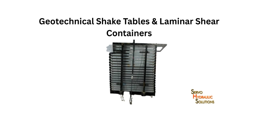
Earthquake simulation shake table prices range from 653–3,000 for small open-source educational stepper platforms and 15,000–45,000 for entry-level commercial units, while custom high-payload servo-hydraulic shake tables typically require custom engineering quotes starting from tens of thousands to several hundred thousand dollars depending on payload, axes (uniaxial vs. multi-DOF), and Hydraulic Power Supply (HPU) capacity. Choosing an open-architecture COTS servo-hydraulic system allows university and commercial labs to match real seismic velocity and force requirements without paying proprietary OEM markups.
To obtain meaningful results, the complete system must be designed around the soil model, container type, actuator force, stroke, frequency range, and test conditions. A geotechnical shake table simulates seismic ground motion under controlled laboratory conditions to study soil mechanics, liquefaction phenomena, and soil-structure interaction.
A geotechnical shake table reproduces seismic ground motion in a lab environment, making it much easier for researchers to study soil behaviour, liquefaction phenomena, and soil-structure interactions.
What Is a Geotechnical Shake Table?
A geotechnical shake table is a laboratory testing platform that applies controlled vibration to soil models and structures. Researchers use it to investigate how soil deposits, foundations, retaining structures, buried pipelines, and buildings respond to earthquake loading.
Unlike a conventional vibration test, where the specimen is usually a solid component, geotechnical testing often involves a soil-filled container. The container, soil, embedded structure, and instrumentation all contribute to the moving mass.
A typical system includes:
- A rigid or laminar soil container.
- One or more servo-hydraulic actuators.
- A reaction structure and supporting foundation.
- A vibration control system.
- Accelerometers and displacement sensors.
- Pore-pressure sensors for saturated soil tests.
- Data acquisition and safety systems.
The right configuration depends on what the laboratory wants to investigate. A small 1g soil model, for example, has different requirements from a centrifuge experiment intended to reproduce prototype stress conditions.
How a Geotechnical Shake Table Works
The shake table applies a programmed motion to a soil container or model assembly. Servo-hydraulic actuators generate the required movement by converting controlled hydraulic pressure and flow into mechanical force and displacement.
The basic testing sequence is:
- Prepare the soil model to the required density and moisture condition.
- Install the model inside the selected container.
- Position the structure, foundation, or other test specimen.
- Install accelerometers, pore-pressure transducers, and displacement sensors.
- Program the required acceleration or displacement time history.
- Run the test while recording the input motion and soil response.
For example, a research team studying a shallow foundation on saturated sand may apply a selected earthquake record to observe settlement, acceleration amplification, and excess pore-water pressure development.
The input motion needs to be checked at the table and, where appropriate, within the soil model. The commanded signal alone does not prove that the intended motion reached the specimen.
Difference Between 1g Shake Tables and Centrifuge Shakers
Both systems study soil response under dynamic loading, but they reproduce different physical conditions.
A 1g shake table tests a model under normal laboratory gravity. A geotechnical centrifuge increases the apparent gravitational acceleration so that a smaller soil model can reproduce important stress conditions associated with a larger prototype.
| Feature | 1g shake table | Centrifuge shaker |
| Gravity condition | Normal Earth gravity | Increased centrifugal acceleration |
| Model scale | Often uses reduced-scale models | Uses reduced-scale models with scaling laws |
| Stress simulation | Limited by normal gravity | Can reproduce prototype-like stress levels |
| Equipment arrangement | Usually a conventional laboratory installation | Must operate within a rotating centrifuge environment |
| Main applications | Soil behaviour, foundations, retaining walls, and earthquake response | Stress-dependent soil behaviour and scaled soil-structure interaction |
A 1g model can be very useful for investigating mechanisms and comparing design configurations. However, it does not automatically reproduce prototype stress levels. Centrifuge modelling is selected when the stress conditions are important to the research objective.
When a Geotechnical Shake Table Is Needed
A geotechnical shake table is useful when researchers need to observe how soil and structures respond to controlled dynamic loading.
Common applications include:
- Soil liquefaction and post-earthquake settlement studies.
- Foundation and pile response under seismic loading.
- Retaining wall and slope stability research.
- Buried pipeline and underground structure testing.
- Soil-structure interaction studies.
- Ground improvement and seismic mitigation research.
Select the system around the test objective, not simply the largest possible payload. A laboratory investigating liquefaction, for instance, may place greater importance on low-frequency motion control, container behaviour, saturation arrangements, and pore-pressure instrumentation than on maximum acceleration alone.
Laminar Shear Containers Explained
A laminar shear container is designed to hold a soil model while allowing controlled horizontal deformation between its layers. Its purpose is to reduce the artificial restraint that a rigid container can impose on moving soil.
This matters because natural soil deposits do not behave like a solid block enclosed by perfectly fixed walls. During earthquake shaking, soil layers deform relative to one another. A suitable container helps reproduce this behaviour more realistically.
What Is a Laminar Soil Box?
A laminar soil box is typically constructed from a series of horizontal frames or rings stacked vertically. These layers are connected or supported using a guiding arrangement that allows relative horizontal movement while maintaining the overall container shape.
The soil is placed inside the box, and the assembly is mounted on the shake table.
Depending on the design, the layers may use bearings, rollers, or other low-friction arrangements. The objective is to allow controlled shear deformation while limiting unwanted vertical movement and excessive distortion.
The exact construction varies with container size, model dimensions, and the required frequency range.
How Laminar Layers Simulate Free-Field Soil
During earthquake shaking, different depths of a soil deposit may experience different horizontal displacements. A laminar container allows its layers to move relative to each other, helping the soil model deform more like free-field shear behaviour.
For example, when a horizontal acceleration is applied at the base, the lower soil layers may move differently from the upper layers. The container’s laminar arrangement accommodates some of this relative movement instead of forcing the entire soil mass against rigid sidewalls.
The design still has limitations. Layer friction, frame stiffness, clearances, and connections can influence the measured response. The container must be designed and calibrated for the intended soil model and test conditions.
Laminar Box vs Rigid Soil Container
| Feature | Laminar soil box | Rigid soil container |
| Sidewall behaviour | Layers can move relative to one another | Walls remain largely fixed |
| Soil deformation | Allows controlled shear deformation | Can restrain lateral soil movement |
| Boundary effects | Designed to reduce some boundary effects | May introduce stronger wall restraint |
| Mechanical complexity | Higher | Generally simpler |
| Maintenance | Moving interfaces need inspection | Fewer moving interfaces |
| Typical use | Dynamic soil deformation and seismic modelling | Tests where rigid boundaries are suitable |
A rigid container is not automatically unsuitable. It can be appropriate for specific research questions, particularly where the boundary condition is intentional or where a simpler test arrangement is required.
The choice should reflect the physical behaviour the experiment needs to reproduce.
When a Laminar Shear Container Is Required
Consider a laminar container when the experiment depends on realistic lateral soil deformation.
Typical situations include:
- Seismic response of layered soil deposits.
- Soil liquefaction studies.
- Foundation-soil interaction under earthquake loading.
- Retaining structures and buried infrastructure.
- Experiments where rigid sidewalls could significantly affect soil response.
Researchers should also consider the model dimensions, soil type, expected shear deformation, drainage arrangement, and instrumentation access before finalising the container.
Soil-Structure Interaction Shake Table Actuators
Actuators are central to the performance of a soil-structure interaction shake table. They must generate the required motion while driving the combined mass of the container, soil, structural model, and associated fixtures.
Selecting actuators based only on the soil model’s weight can lead to an undersized system. The complete moving assembly and its dynamic requirements need to be considered.
How Servo-Hydraulic Actuators Drive Soil Models
Servo-hydraulic actuators use pressurised hydraulic fluid to generate controlled mechanical movement. A servo valve regulates fluid flow to the actuator, allowing the control system to command force, velocity, or displacement according to the test requirements.
A typical arrangement includes:
- Hydraulic power unit.
- Servo valves and actuator cylinders.
- Hydraulic hoses and manifolds.
- Accumulators where required.
- Position and force feedback sensors.
- Real-time control hardware.
- Safety and monitoring equipment.
During testing, the controller compares the measured response with the target command and adjusts the actuator input. This closed-loop operation helps reproduce the required motion.
For geotechnical applications, the actuator must also handle changing loads caused by soil behaviour, container dynamics, and structural interaction.
Matching Actuator Force to Container and Soil Mass
The actuator force must account for the complete moving assembly.
A preliminary inertial force estimate is:
[
F=m\times a
]
Where:
- (F) = inertial force in newtons.
- (m) = total moving mass in kilograms.
- (a) = required acceleration in metres per second squared.
Consider an illustrative setup:
| Component | Mass |
| Laminar container | 800 kg |
| Soil model | 1,500 kg |
| Structural model | 200 kg |
| Fixtures and instrumentation | 100 kg |
| Total moving mass | 2,600 kg |
If the target acceleration is 0.3g:
[
F=2600\times(0.3\times9.81)
]
[
F=7651.8\ N
]
The estimated inertial force is approximately 7.65 kN.
This is a preliminary estimate, not a final actuator rating. Actual selection must account for the container and structural dynamics, friction, hydraulic and mechanical losses, required waveform, control margin, and any additional forces from the test arrangement.
For multiple actuators, force sharing also depends on their positions, control strategy, and structural load distribution.
Actuator Stroke and Displacement Requirements
Stroke is the maximum available actuator travel. It must be sufficient to reproduce the required displacement without reaching mechanical limits.
For sinusoidal motion, displacement amplitude is related to acceleration and frequency by:
[
x=\frac{a}{(2\pi f)^2}
]
Where:
- (x) = displacement amplitude in metres.
- (a) = acceleration amplitude in metres per second squared.
- (f) = frequency in hertz.
This relationship illustrates why low-frequency testing can require substantial displacement.
For instance, a low-frequency motion with a relatively modest acceleration may require more travel than a higher-frequency motion at the same acceleration. Earthquake records are not simple constant-frequency sine waves, so the actual displacement demand should be calculated from the complete input time history.
Specify whether the quoted stroke is total peak-to-peak travel or one-sided amplitude. Confusing these values can cause serious procurement errors.
Velocity, Acceleration, and Frequency Limits
Force and stroke are only part of actuator selection. The system must also achieve the required velocity and acceleration across the intended frequency range.
For sinusoidal motion:
[
v_{max}=2\pi f x
]
And:
[
a_{max}=(2\pi f)^2x
]
A system may have sufficient force at low frequency but reach its velocity or hydraulic flow limit at higher frequency.
For earthquake simulations, the actuator must reproduce the important characteristics of the target record. These may include peak acceleration, velocity, displacement, frequency content, and duration.
The usable operating envelope should be evaluated under the actual payload conditions.
Single vs Multiple Actuators
A single actuator can suit a uniaxial soil model when the required movement and load are within its operating limits.
Multiple actuators may be needed when:
- The moving assembly is large or heavy.
- Higher force or flow capacity is required.
- The system needs controlled movement at more than one location.
- The research requires more than one excitation direction.
- The table design needs coordinated force application.
Multiple actuators introduce additional control and mechanical considerations. Their alignment, force sharing, synchronisation, and interaction with the table structure must be properly designed.
More actuators do not automatically mean better performance. The configuration should follow the required degrees of freedom, multi-axis motion requirements, and test objectives.
Servo-Hydraulic Centrifuge Shaker Specs
A servo-hydraulic centrifuge shaker is designed to apply controlled dynamic motion to a soil model while the centrifuge operates at an elevated acceleration level.
Unlike a conventional laboratory shake table, this equipment must operate in a rotating environment. Its mechanical layout, hydraulic connections, control system, and payload limits need to account for centrifugal acceleration and the available space inside the centrifuge.
How Centrifuge Shakers Differ From 1g Shake Tables
A conventional 1g shake table operates in a stationary laboratory environment. A centrifuge shaker must generate vibration while the soil model is subjected to increased apparent gravity.
The centrifuge creates a higher stress environment within the reduced-scale soil model. The shaker then introduces dynamic motion to study earthquake response under those conditions.
This requires careful coordination between centrifuge operation and shaker performance. The shaker must fit within the available platform, withstand the operating environment, and reproduce the required input motion.
Centrifuge G-Level and Scaling Requirements
Centrifuge tests use scaling laws to relate model behaviour to prototype behaviour. Under idealised geometric scaling at a centrifuge acceleration of (N g), a model length is commonly scaled by a factor of (1/N) relative to the prototype.
For example, a 1:50 geometric model is commonly tested at 50g to reproduce relevant stress conditions, subject to the assumptions and limitations of the chosen modelling approach.
Dynamic time scaling also matters. In common centrifuge modelling approaches, model time is scaled relative to prototype time. Researchers must use the scaling relationships appropriate to the soil behaviour and test objective.
The shaker input must therefore be specified in model-scale terms and checked against the centrifuge’s operating conditions. Simply applying a full-size earthquake record without scaling is not a valid procedure.
Actuator Force, Stroke, and Frequency in Centrifuge Testing
Centrifuge shaker actuators must generate the required motion while accounting for the mass of the model container, soil, structure, and moving hardware.
Their design must consider:
- Required acceleration time history.
- Available actuator stroke.
- Velocity and acceleration limits.
- Dynamic payload.
- Operating frequency range.
- Centrifuge g-level.
- Mechanical and hydraulic constraints.
The relationship between force, mass, and acceleration remains useful for preliminary sizing, but the final design must also account for the operating environment and system dynamics.
Hydraulic Supply, Accumulators, and Control Systems
A centrifuge shaker may use a hydraulic power unit and accumulators to provide the required flow and pressure.
Accumulators can help supply short-duration peak flow demands that exceed the pump’s immediate delivery capability. Their sizing depends on actuator displacement, velocity, duty cycle, pressure range, and hydraulic circuit design.
The control system should match the centrifuge’s operating arrangement. It must support reliable command generation, feedback measurement, data recording, and safety interlocks.
Hydraulic hoses, electrical connections, and instrumentation cables must be routed and secured for centrifuge operation. Their movement and loading should be considered during system design.
Payload and Container Mass Limits
Centrifuge payload limits are particularly important because the shaker, container, soil, structure, and fixtures all contribute to the installation’s total mass and geometry.
The available payload may be restricted by:
- Centrifuge capacity.
- Platform dimensions.
- Radial position of the assembly.
- Dynamic forces during shaking.
- Structural strength and attachment points.
- Hydraulic and electrical service arrangements.
The shaker supplier and centrifuge facility should verify the complete configuration together. A component that fits within the platform dimensions may still exceed the allowable mass or dynamic loading limits.
Soil Liquefaction Vibration Testing System
A soil liquefaction vibration testing system is used to study how saturated, loose or contractive soil responds to cyclic loading. Under suitable conditions, shaking can generate excess pore-water pressure and reduce effective stress, potentially causing a substantial loss of soil strength and stiffness.
These tests help researchers investigate ground failure, foundation settlement, lateral spreading, and other earthquake-related hazards.
What Is Soil Liquefaction Testing?
Soil liquefaction testing examines how soil behaves when cyclic loading increases pore-water pressure.
In saturated granular soils, repeated shaking can cause the soil skeleton to transfer some stress to the pore water. As excess pore pressure rises, effective stress decreases.
The effective stress relationship is:
[
\sigma’=\sigma-u
]
Where:
- (\sigma’) = effective stress.
- (\sigma) = total stress.
- (u) = pore-water pressure.
When effective stress becomes very low, the soil may lose much of its ability to resist deformation. The actual response depends on soil density, confining stress, drainage, loading history, and other conditions.
Specimen Saturation and Pore-Pressure Measurement
A reliable liquefaction experiment requires careful specimen preparation and saturation.
The preparation process may involve controlled soil placement, density measurement, saturation procedures, and consolidation under the required stress conditions.
Pore-pressure transducers are installed at selected depths to monitor pressure changes during shaking. Their location and response characteristics matter because pressure can vary throughout the soil deposit.
Researchers should document:
- Soil type and particle-size distribution.
- Relative density or void ratio.
- Saturation procedure.
- Initial effective stress.
- Consolidation conditions.
- Sensor locations and calibration.
Incomplete saturation or inconsistent preparation can affect the results, making repeatability difficult.
Input Motion Requirements for Liquefaction Studies
The input motion should reflect the research objective and the expected loading conditions.
Relevant parameters include:
- Peak ground acceleration.
- Frequency content.
- Duration.
- Number of significant loading cycles.
- Displacement and velocity demand.
- Waveform characteristics.
Two earthquake records with similar peak acceleration can produce different soil responses because their frequency content and duration differ.
The table control system should reproduce the target motion accurately under the loaded test condition. Researchers should also record the actual base input so that the measured soil response can be interpreted correctly.
Instrumentation for Liquefaction Testing
Well-instrumented tests help researchers understand what happened inside the soil, not just what motion was applied at the base.
Common instrumentation includes:
- Accelerometers at different soil depths.
- Pore-pressure transducers.
- Displacement sensors.
- Load cells where structural forces are measured.
- Strain gauges on structural models.
- Data acquisition systems with synchronised channels.
Sensor cables should be arranged so they do not interfere with soil deformation or introduce unwanted mechanical restraint.
Safety and Drainage Requirements
Saturated soil models introduce practical risks that need attention before testing begins.
The container must prevent leakage and safely retain the soil-water mixture. Drainage and overflow arrangements should be designed around the test procedure, particularly where water levels or pore pressure are expected to change.
Check the following before operation:
- Container sealing and leak resistance.
- Drainage and water collection arrangements.
- Electrical protection around wet areas.
- Safe access for specimen preparation.
- Emergency stop and shutdown procedures.
- Hydraulic hose and cable protection.
The system should also have a defined procedure for draining, unloading, and removing the soil after testing.
Laminar Soil Box Shake Table Requirements
A laminar soil box shake table must be specified as one integrated mechanical and testing system. The container cannot be treated as a simple accessory because its mass, stiffness, movement, and boundary conditions directly affect the experiment.
Container Size, Mass, and Centre of Gravity
Container dimensions should accommodate the soil deposit, structural model, instrumentation, and required clearance.
The container’s own mass must be included in actuator calculations. Its centre of gravity also affects the loads transferred to the table and supporting structure.
A wide container may offer more space but can introduce greater structural demands. A tall assembly may increase overturning moment, particularly during horizontal acceleration.
Layer Stiffness, Friction, and Boundary Conditions
The stiffness of each laminar layer and the friction between moving interfaces influence the container’s behaviour.
If layers are too stiffly connected, they may restrict relative movement. If they move too freely, the container may fail to provide the intended boundary support.
Designers should review layer spacing, guiding arrangements, bearing or roller characteristics, clearances, and lateral stability. The objective is controlled movement that supports the research model without creating excessive mechanical interference.
Base Connection and Load Transfer
The base connection transfers the shaker input into the container and soil model. It must be sufficiently strong and stiff to avoid unwanted movement or local deformation.
Check:
- Mounting bolt patterns.
- Base plate stiffness.
- Connection alignment.
- Load transfer through the frame.
- Dynamic force capacity.
- Accessibility for installation and inspection.
The container must remain securely attached throughout the test, including during high-acceleration events.
Instrumentation and Sensor Integration
Consider instrumentation during the container design stage rather than adding it as an afterthought.
Plan sensor locations, cable routing, connector access, and protective arrangements. Sensors should be installed without creating significant local stiffness changes or interfering with the movement of laminar layers.
Drainage, Saturation, and Leakage Control
For saturated soil tests, the container must accommodate the required water level and drainage arrangement.
Seals, joints, and penetrations should be selected for the expected pressure and movement conditions. Cable openings and sensor connections are common locations that need careful attention.
A pre-test leakage inspection is essential before filling the container and beginning the experiment.
How to Specify a Geotechnical Shake Table System
A good specification gives the equipment supplier enough information to design a system around the actual research requirements. It should describe the soil model, container, input motion, payload, and operating environment rather than relying on a single maximum force figure.
Define the Soil Model and Test Objective
Start with the research question.
Is the laboratory studying liquefaction, foundation response, retaining walls, slope behaviour, or soil-structure interaction? Will the model operate at 1g or inside a centrifuge?
Document soil type, model dimensions, density, saturation, structural components, required test orientations, and expected loading conditions.
Calculate Container, Soil, and Structure Mass
Prepare a complete mass schedule covering:
- Container and laminar frames.
- Soil and water.
- Structural model.
- Base plate and fixtures.
- Instrumentation and accessories.
- Other moving components.
Use the total moving mass for preliminary force calculations. Also document the centre of gravity and any eccentric loading.
Match Actuators to Required Motion
Specify the complete motion requirement, including acceleration, displacement, velocity, frequency range, waveform, and duration.
Ask the supplier to demonstrate that the proposed actuator can achieve the required motion with the complete payload installed.
For multiple actuators, include the required degrees of freedom, synchronisation, force distribution, and control strategy.
Review Hydraulic Supply and Control System
Check hydraulic pressure, flow, accumulator requirements, oil cooling, filtration, and duty cycle.
The controller should support the required waveform reproduction, feedback, data acquisition, and safety functions. For centrifuge applications, all hydraulic and electrical arrangements must also suit the rotating environment.
Compare Complete System Quotations
Compare quotations using the same technical specification. Look beyond the actuator force rating and request details of the complete system.
A useful quotation should identify:
- Shaker and actuator specifications.
- Container design and payload limits.
- Hydraulic power and control equipment.
- Reaction base and foundation requirements.
- Instrumentation interfaces.
- Installation and commissioning.
- Training and maintenance support.
- Performance verification under representative loading.
This makes it easier to identify missing components and compare suppliers fairly.
Frequently Asked Questions
What Is a Geotechnical Shake Table?
A geotechnical shake table is a laboratory platform that applies controlled, earthquake-like motion to soil models and structures. It helps researchers investigate soil deformation, liquefaction, foundation response, and soil-structure interaction.
What Is a Laminar Shear Container?
A laminar shear container is a soil-testing box made from stacked horizontal layers that can move relative to one another. It is designed to allow controlled lateral soil deformation during dynamic testing.
What Is the Difference Between a Laminar Box and a Rigid Container?
A laminar box allows relative movement between its layers to accommodate soil shear deformation. A rigid container has largely fixed sidewalls, which can impose stronger lateral boundary restraint on the soil model.
When Is a Laminar Soil Box Needed?
A laminar soil box is useful when the experiment requires realistic lateral deformation of a soil deposit. It is commonly considered for seismic soil response, liquefaction, and soil-structure interaction studies where rigid boundaries could influence the results.
What Is Soil Liquefaction Testing?
Soil liquefaction testing investigates how cyclic loading affects pore-water pressure and effective stress in saturated soil. Researchers use it to study potential loss of soil strength, settlement, and earthquake-related ground deformation.
How Is Actuator Force Calculated for a Soil Shake Table?
A preliminary inertial force estimate uses (F=m\times a), where mass includes the container, soil, structure, fixtures, and moving components. Final actuator sizing must also consider dynamic behavior, friction, hydraulic losses, waveform requirements, and operating margins.
What Stroke Is Needed for Geotechnical Shake Table Testing?
Required stroke depends on the input motion’s displacement demand, frequency, acceleration, and duration. Calculate it from the target time history and check it against the actuator’s usable travel under the full test payload.
What Is the Difference Between a 1g Shake Table and a Centrifuge Shaker?
A 1g shake table tests a soil model under normal gravity. A centrifuge shaker applies dynamic motion while the model experiences increased apparent gravity, helping researchers reproduce important prototype stress conditions in a reduced-scale model.
Conclusion
A geotechnical shake table and laminar shear container must be specified as one integrated system. Define the soil model, container type, total moving mass, centre of gravity, actuator force, stroke, frequency range, and instrumentation requirements before purchasing. A well-matched system delivers reliable soil-structure interaction and liquefaction testing without unnecessary cost or complexity. To discuss engineered custom shake tables or complete testing systems tailored to your laboratory’s payload and facility limits, reach out to our engineering team for a project-specific assessment.
Planning a Geotechnical Shake Table or Soil-Structure Test Setup?
Whether you are specifying servo-hydraulic actuators for a laminar shear container, configuring a 1g or centrifuge seismic rig, or evaluating liquefaction testing requirements, our engineers can help size your system accurately.