- Have any Query
- (303) 807-1061
- doug@servohydraulicsolutions.com

Open Frame vs Enclosed Hydraulic Power Supplies for Labs

Earthquake Simulation Shake Tables: Types, Applications, and Selection Guide
November 2, 2026
Reduce Setup Time for Industrial Seismic Qualification Testing
November 4, 2026An open-frame hydraulic power supply offers easy access to pumps, motors, filters, and other components. In contrast, an enclosed hydraulic power supply provides better protection from noise, oil mist, and the surrounding lab environment. The right choice depends on your test loads, maintenance requirements, available space, hydraulic oil cleanliness targets, and how closely the power unit must operate alongside sensitive testing equipment.
For structural testing laboratories, the decision involves more than choosing between an exposed frame and a cabinet. A well-designed hydraulic power system must deliver stable pressure and flow, support demanding actuator movements, control oil temperature, and protect servo valves from contamination. These requirements matter most when a laboratory operates shake tables, servo-controlled actuators, earthquake simulators, or other equipment that must reproduce precise dynamic movements.
Let’s look at how each design works, where it performs best, and what to consider when planning a reliable laboratory hydraulic system.
Open Frames vs Enclosed Hydraulic Power Supplies for Labs
What Is a Laboratory Hydraulic Power Supply?
A laboratory hydraulic power supply (HPS) converts electrical energy into pressurized hydraulic fluid that operates actuators and other hydraulic equipment. In a structural testing laboratory, it supplies the force and flow needed to move test specimens, simulate mechanical loads, and reproduce controlled motion during experiments.
A Laboratory Hydraulic Pumping System may serve one test frame or distribute hydraulic power to several test stations. Its design depends on the connected equipment’s pressure and flow requirements, the required operating duration, and whether multiple actuators must work simultaneously.
Unlike a basic industrial power pack, a system intended for servo-hydraulic testing must also support predictable dynamic performance. Pressure stability, fluid cleanliness, cooling capacity, and control response all affect test quality and repeatability.
What a Servo Hydraulic Power Unit Does
A Servo Hydraulic Power Unit supplies pressurized oil to servo valves and hydraulic actuators. The valves regulate oil flow into and out of the actuator chambers, allowing a controller to command displacement, velocity, force, or a programmed motion profile.
For example, a structural engineering laboratory might use hydraulic actuators to apply cyclic lateral loads to a beam-column connection. The power unit supplies the hydraulic energy, while the controller and servo valves determine how the actuator follows the required loading sequence.
The power supply does not generate the test waveform. Accurate motion depends on the combined performance of the power unit, hydraulic circuit, actuator, servo valve, controller, sensors, and test fixture.
Main Components of an HPS
A typical laboratory HPS includes the following components:
- Hydraulic pump: Produces the required fluid flow at the operating pressure.
- Electric motor: Drives the pump.
- Reservoir: Stores hydraulic oil and provides space for air release and heat dissipation.
- Filtration system: Removes particulate contamination from the hydraulic fluid.
- Pressure-control components: Include relief valves and other devices that help keep operation within permitted limits.
- Cooling system: Removes heat generated during hydraulic operation.
- Accumulators: Store pressurized fluid when the design requires additional flow support or to manage pressure pulsations.
- Manifolds and distribution piping: Route hydraulic oil to the connected test equipment.
- Sensors and monitoring devices: Measure parameters such as pressure, temperature, and filter condition.
- Electrical and control interfaces: Coordinate pump operation, interlocks, alarms, and system status.
Not every installation needs the same configuration. A compact power unit serving one actuator may be relatively simple, while a centralised system supplying multiple high-flow test stations requires more detailed distribution, cooling, and control planning.
Where Hydraulic Power Is Needed in Labs
Hydraulic systems are common in laboratories that need substantial force or controlled mechanical movement.
Typical applications include:
- Structural testing of beams, columns, joints, and building components.
- Earthquake simulation using servo-hydraulic shake tables.
- Fatigue and durability testing under repeated loading.
- Testing of bridges, civil engineering structures, and structural connections.
- Material and component testing using hydraulic test frames.
- Automotive and aerospace component testing.
- Multi-axis actuator systems that apply simultaneous loads in different directions.
The required power supply depends on the application. A laboratory performing occasional low-speed loading tests may have very different requirements from a facility running continuous, high-frequency dynamic tests.
Open Frame vs Enclosed Hydraulic Power Supplies
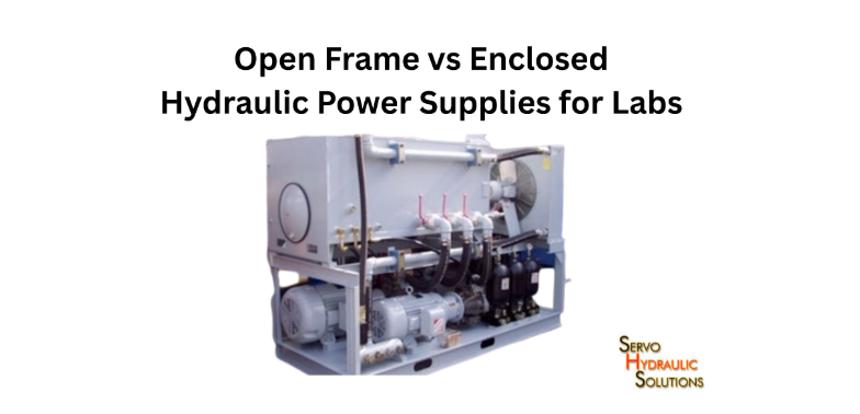
The main difference between an open frame and an enclosed HPS is how the equipment is arranged and protected. An open frame exposes most major components for inspection and service, whereas an enclosed unit places them inside a cabinet, housing, or acoustic enclosure.
Neither arrangement is automatically more reliable. Component quality, hydraulic circuit design, filtration, cooling, installation, and maintenance practices matter just as much as the external structure.
What Is an Open Frame Hydraulic Power Supply?
An Open Frame Hydraulic Power Supply mounts components on an accessible structural frame rather than enclosing the entire assembly within a cabinet.
Pumps, motors, reservoirs, filters, manifolds, and pipework can often be inspected directly. This makes the arrangement useful in dedicated pump rooms, industrial test facilities, and structural laboratories where maintenance access is a priority.
Common advantages include:
- Convenient access to filters, hoses, pumps, and valves.
- Easier visual inspection for leaks and loose connections.
- Flexible component arrangement and future modifications.
- Straightforward integration with large reservoirs and cooling equipment.
- More options for custom piping and service connections.
The trade-off is that the surrounding room must accommodate noise, heat, potential oil mist, and appropriate protection for exposed components.
What Is an Enclosed Hydraulic Power Supply?
An enclosed hydraulic power supply places its components within a cabinet or protective housing. Depending on the design, the enclosure may provide acoustic insulation, ventilation, access panels, leak containment, and protection from dust or accidental contact.
This configuration can be suitable when the power unit is installed near a testing area, in a shared laboratory, or in a space where exposed machinery would create operational difficulties.
Typical advantages include:
- Reduced transmission of airborne pump and motor noise when the enclosure is acoustically designed.
- Protection against accidental contact with moving or hot components.
- Better control over access to selected equipment.
- Potential integration of oil containment and ventilation features.
- A cleaner external appearance in occupied laboratory areas.
However, an enclosure does not automatically eliminate noise, prevent leaks, or maintain oil cleanliness. Those outcomes depend on the enclosure’s construction and the complete system’s engineering.
Key Differences at a Glance
| Factor | Open frame HPS | Enclosed HPS |
|---|---|---|
| Maintenance access | Generally straightforward | Depends on access panels and layout |
| Noise control | Usually requires room-level treatment | Can include acoustic treatment |
| Heat management | Components are easier to access for inspection; cooling still needs design | Ventilation and heat removal need careful planning |
| Contamination protection | Exposed components need suitable protection | Housing can reduce environmental exposure |
| Oil leak management | Requires appropriate floor or bund containment | May incorporate an integrated containment arrangement |
| Installation | Often suited to dedicated plant rooms | Can suit controlled or occupied laboratory areas |
| Customization | Often convenient for bespoke layouts | Changes may require enclosure modifications |
| Space requirements | Frame footprint plus service clearance | Cabinet footprint plus door and ventilation clearance |
| Best fit | Accessible plant rooms and custom systems | Noise-sensitive or space-managed installations |
The most useful comparison is not simply which design looks cleaner. It is which configuration makes the complete hydraulic system easier to operate, inspect, maintain, and expand safely.
Open Frame Hydraulic Power Supply: Benefits and Limits
An open frame design is particularly useful when a laboratory needs a custom hydraulic arrangement and expects regular access to its components. It can simplify service work, but it also places greater responsibility on the facility to manage the surrounding environment.
Easier Access for Maintenance
Routine maintenance becomes more convenient when technicians can reach filters, pumps, motors, fittings, and pressure-control components without removing large enclosure panels.
For example, a laboratory that changes hydraulic filters frequently may benefit from an open-frame arrangement with clearly accessible filter housings and enough space to remove components without disturbing nearby pipework.
Good accessibility can reduce maintenance time and make it easier to identify oil leaks, damaged hoses, unusual vibration, and loose connections. It also helps technicians inspect equipment before a demanding test campaign.
That advantage disappears if components are crowded together. An open frame should still provide safe access, appropriate lifting provisions, clear identification, and enough room to service each item.
Better Heat Dissipation Options
Open frame installations make it easier to arrange external heat exchangers, cooling circuits, and ventilation around the power unit. However, an exposed frame does not automatically run cooler.
Hydraulic oil heats up because of pump losses, pressure drops, throttling, leakage, and other inefficiencies. A system that operates for long periods or supplies several actuators may need a dedicated oil cooler even when installed in a well-ventilated room.
Cooling capacity should be based on expected heat generation and the laboratory’s operating conditions. Oil temperature must remain within the acceptable range for the fluid, seals, pumps, valves, and other components.
Best Uses in Pump Rooms
Open frame units often suit dedicated hydraulic plant rooms where noise and heat can be managed separately from the test area.
They are worth considering when:
- The system uses large pumps, reservoirs, or external cooling equipment.
- Maintenance teams need frequent access to components.
- The installation requires customized piping and manifolds.
- Several actuators share a common hydraulic source.
- The facility expects future capacity changes or equipment upgrades.
For a structural testing facility, a centralized open frame system may be practical when the hydraulic power unit is located away from the test floor and supplies several test bays through engineered distribution lines.
Noise, Oil Mist, and Housekeeping Considerations
An open-frame power supply can expose technicians and nearby occupants to pump and motor noise and structure-borne vibration. Noise levels depend on pump type, operating pressure, flow, mounting, and the surrounding room.
Oil mist can also be a concern where leakage, fluid handling, or unsuitable operating conditions produce airborne oil droplets. A well-designed hydraulic circuit should minimize leakage and unnecessary oil agitation rather than relying on the enclosure alone to manage these issues.
Good housekeeping includes:
- Providing suitable spill containment and leak-response materials.
- Keeping walkways clear around the frame.
- Protecting exposed hoses and fittings from impact.
- Keeping filter-change and fluid-transfer areas clean.
- Following the manufacturer’s procedures for oil handling and disposal.
An open frame can be an excellent engineering choice, provided the laboratory is equipped to manage the environment around it.
Enclosed Hydraulic Power Supply: Benefits and Limits
An enclosed HPS is often attractive when the hydraulic unit must operate closer to technicians, researchers, or sensitive equipment. Its effectiveness depends on how well the enclosure addresses access, ventilation, noise, and containment.
Lower Noise and Cleaner Lab Environment
An acoustically designed enclosure can reduce airborne noise from the pump and motor. This can improve conditions in laboratories where researchers need to communicate, monitor instruments, or work near a test setup.
The result depends on details such as panel construction, ventilation openings, door seals, vibration isolation, and noise transmission through the floor and connected pipes. Simply placing a pump inside a metal cabinet may have little effect if the enclosure is not designed for acoustic performance.
Noise control should also consider the pump’s mounting and hydraulic pressure pulsations. Flexible connections, suitable vibration isolation, and properly supported piping may be necessary to control transmitted vibration.
Integrated Filtration and Containment
An enclosed power unit can integrate filter housings, access points, drip trays, and monitoring devices into a compact package. This can help organise the installation and reduce exposure to dust or accidental contact.
Still, Micro Clean Hydraulic Filtration is a filtration strategy, not an automatic benefit of enclosing a power unit. Oil cleanliness depends on the filter arrangement, filter efficiency, sealing, fluid handling, component wear, and maintenance practices.
Likewise, a cabinet only provides effective leak containment when its base and drainage arrangements are designed for that purpose. Any containment provision should suit the possible fluid volume and applicable site requirements.
Compact Placement Near Test Equipment
An enclosed unit can be useful when a laboratory has limited plant-room space or needs a visually organised installation near a test frame.
Shorter hydraulic lines may reduce pressure losses and simplify installation, but placing the HPS near the specimen isn’t always best. Pump noise, heat, maintenance access, vibration, and safety clearances must be considered together.
For example, a compact enclosed unit may work well for a single material-testing frame. A high-flow shake table system may be better located in a separate plant room, even if the enclosure itself is compact.
Service Access and Heat Management Limits
Enclosures can slow routine service when filters, valves, or electrical components are hard to reach. Narrow doors and tightly arranged components can turn a simple filter replacement into a lengthy maintenance task.
Heat removal also requires careful attention. Pumps and motors generate heat, and an enclosure can trap it if airflow and cooling are insufficient.
Before selecting an enclosed unit, check:
- Filter and component removal clearances.
- Access to isolation points and emergency stops.
- Ventilation requirements and cooling capacity.
- Internal operating temperatures.
- Oil leak detection and containment provisions.
- Space to open panels and safely service the equipment.
A well-designed enclosure should make the installation easier to manage, not hide problems or make routine maintenance unnecessarily difficult.
Micro Clean Hydraulic Filtration for Servo Systems
Hydraulic fluid cleanliness is essential in servo-hydraulic laboratories because particulate contamination can affect small clearances inside precision valves. A suitable filtration strategy protects components, maintains predictable operation, and reduces avoidable wear.
The required cleanliness level depends on the installed components and the manufacturer’s specifications. No single filtration arrangement or cleanliness target suits every laboratory HPS.
Why Oil Cleanliness Matters
Hydraulic oil carries energy, lubricates moving components, and helps transfer heat. If the oil contains excessive particles, moisture, or degradation products, it can cause wear, valve sticking, surface damage, and unreliable system operation.
In a servo-hydraulic circuit, contamination can be especially troublesome because precision valve components operate with very small clearances. A contaminated valve may respond inconsistently, affecting actuator control and test repeatability.
Contamination can enter during initial filling, maintenance, hose replacement, component installation, or through inadequate reservoir breathing and sealing. Internal wear can also generate particles during operation.
How Micro Clean Filtration Protects Servo Valves
Micro Clean Hydraulic Filtration means maintaining fine particulate control through proper filtration, fluid handling, and monitoring. Filter selection should be based on the required cleanliness target and the performance specifications of the components being protected.
A filter’s nominal micron rating alone does not tell the whole story. Engineers should review its efficiency, often expressed as a beta ratio, along with its dirt-holding capacity, pressure drop, bypass arrangement, and compatibility with the hydraulic fluid.
Effective filtration helps:
- Reduce particulate contamination reaching precision valves.
- Limit abrasive wear in pumps and actuators.
- Maintain fluid cleanliness over the operating cycle.
- Reduce contamination introduced during servicing.
- Support reliable operation of demanding servo-hydraulic equipment.
Fine filtration cannot compensate for poor maintenance, contaminated replacement oil, damaged seals, or an unsuitable hydraulic circuit.
Pressure, Return, and Off-Line Filtration
Different filter locations serve different purposes.
| Filtration type | Typical location | Main purpose | Design consideration |
|---|---|---|---|
| Pressure filtration | Downstream of the pump in a suitable pressure line | Protects sensitive downstream components | Must withstand the applicable pressure and flow conditions |
| Return filtration | In the return line to the reservoir | Captures contamination returning from the circuit | Must accommodate return flow and pressure transients |
| Off-line filtration | In a separate circuit that circulates oil through a filter | Provides continuous or scheduled fluid cleaning independent of the main circuit | Requires appropriate flow, fluid compatibility, and operating controls |
| Reservoir breathing filtration | At the reservoir’s air exchange point | Reduces airborne contamination entering as oil level or temperature changes | Must suit the reservoir’s breathing and moisture-control needs |
Not every system requires all these arrangements. A hydraulic designer should select filtration locations according to the circuit layout, component sensitivity, pump specifications, and contamination-control strategy.
Monitoring Cleanliness and Filter Condition
A filter is only useful when it is correctly installed and maintained. Laboratories should establish a fluid-cleanliness target, monitor oil condition, and replace filter elements according to suitable indicators and maintenance procedures.
Useful practices include:
- Checking differential-pressure indicators where provided.
- Sampling oil to measure particulate cleanliness when appropriate.
- Inspecting fluid for signs of degradation or water contamination.
- Using clean transfer equipment when adding or replacing oil.
- Keeping filter housings sealed during servicing.
- Recording filter changes, oil samples, and maintenance findings.
ISO 4406 is widely used to classify hydraulic fluid particulate cleanliness. The required code should be determined from the manufacturer’s requirements for the most contamination-sensitive components and the operating conditions. Do not assume one ISO code is correct for every servo-hydraulic system.
Laboratory Hydraulic Pumping System Design
A reliable Laboratory Hydraulic Pumping System is designed around the actual demands of the test equipment. Pump selection is only one part of the process; engineers must also consider simultaneous actuator demand, fluid storage, cooling, pressure stability, distribution losses, and future maintenance.
Centralized Pump Room vs Local HPS
A centralized pump room supplies hydraulic power to multiple test stations through a shared distribution system. This can simplify equipment management and keep major pumps, reservoirs, cooling units, and filtration systems outside the immediate testing area.
Its main benefits include centralized maintenance, reduced equipment duplication, and the ability to serve different actuators from a shared supply. However, it also requires careful sizing of the distribution network and coordination of simultaneous demand.
A local HPS serves one machine or a small group of nearby actuators. It can simplify installation and limit the hydraulic lines needed, but several local units may increase the number of components, maintenance tasks, and noise sources across a facility.
| Consideration | Centralized system | Local system |
|---|---|---|
| Multiple test stations | Often well suited | May require separate units |
| Maintenance | Concentrated in one area | Distributed across the facility |
| Hydraulic distribution | More extensive piping | Usually shorter local lines |
| Expansion | Depends on spare capacity and distribution design | May require adding or upgrading units |
| Failure impact | A shared failure can affect several stations | Failure may be limited to one station |
| Initial planning | More complex system-level design | Simpler for a small, dedicated test |
A centralized system is not automatically more efficient. Its value depends on the diversity of test demand, distance between stations, redundancy requirements, and total operating cost—and where existing multi-station units need updated motor controls, manifolds, or station interlocks, a targeted hydraulic power supply retrofit can address operational limitations without replacing the entire power unit.
Sizing Flow, Pressure, and Reservoir Capacity
The HPS must supply enough pressure and flow for the required actuator performance. Pressure relates to the force an actuator can produce, while flow affects how quickly the actuator can move.
For a simplified hydraulic cylinder:
- Force is approximately pressure multiplied by the effective piston area.
- Flow is approximately effective piston area multiplied by piston velocity.
Actual calculations must account for the rod-side area where applicable, friction, pressure losses, actuator geometry, and the operating conditions of the circuit.
Sizing the pump solely from the maximum force rating can produce an unsuitable system. A test may require high force at low speed, high speed at lower force, or simultaneous movement of multiple actuators. Those scenarios can have very different flow requirements.
Reservoir capacity should also suit the circuit’s fluid volume, heat-management strategy, air-release requirements, and manufacturer’s recommendations. A larger reservoir does not replace proper cooling or filtration.
Cooling, Accumulators, and Pressure Control
Hydraulic systems generate heat as fluid passes through pumps, valves, and restrictions. A cooling system must remove enough heat to keep the oil within its permitted operating range under the expected duty cycle.
Depending on the installation, cooling may use an air-cooled heat exchanger, a water-cooled unit, or another suitable arrangement. The selection depends on heat load, room conditions, water availability, maintenance requirements, and the required oil temperature.
Accumulators can support transient flow demand, help manage pressure pulsations, or provide stored hydraulic energy where the design calls for it. They must be correctly sized, installed, maintained, and protected against applicable hazards. They are not a universal solution for an undersized pump.
Pressure-control devices, relief valves, monitoring sensors, and appropriate interlocks help keep the system operating within its design limits.
Redundancy and Maintenance Planning
Some laboratories cannot afford an extended interruption when a hydraulic component fails. In those facilities, redundancy may involve standby pumps, parallel supply arrangements, isolation valves, or other measures that allow selected maintenance activities without shutting down the entire system.
Redundancy should be designed around the consequences of failure. A small unit serving one test frame may not need the same arrangement as a centralised HPS that supplies several high-value testing stations.
Maintenance planning should cover filter replacement, oil sampling, cooling-system inspection, pump checks, hose condition, leak detection, and the availability of critical spare parts. Access to service points should be considered during the original layout, not after installation.
Structural Testing HPS Design
Structural Testing HPS Design focuses on delivering hydraulic power to actuators under the operating conditions required for structural experiments. These systems may need to support large forces, rapid changes in flow demand, multiple actuators, and extended test sequences.
The design must account for both the power supply and the hydraulic distribution network.
Matching HPS Capacity to Actuators
Engineers should calculate the pressure and flow demands of the connected actuators under the planned test conditions. Where several actuators operate together, their combined demand and timing must be considered.
For example, a multi-actuator structural test may apply vertical load while simultaneously pushing a specimen laterally. The HPS must meet the required flow demand without unacceptable pressure fluctuations or reduced actuator performance.
The calculation should account for actuator dimensions, required force, speed, stroke, operating pressure, expected duty cycle, and any simultaneous movement. The control strategy and test waveform can also affect the system’s dynamic demand.
A system that works for slow static loading may not suit high-speed cyclic or earthquake-simulation testing.
Hydraulic Piping and Distribution Layout
Pipes and hoses must carry the required flow while keeping pressure losses and other hydraulic effects within acceptable limits. Line diameter, length, fittings, bends, fluid properties, and flow velocity all influence the result.
For structural laboratories, distribution lines may connect a central pump room to test bays with different actuator requirements. Engineers should consider the route, pressure rating, support arrangement, accessibility, expansion, and safe isolation of each branch.
Poorly supported piping can transmit vibration or experience unnecessary mechanical stress. Undersized lines can create excessive pressure losses and heating, while unsuitable hose arrangements can introduce movement or fatigue concerns.
The final layout should be reviewed against the required pressure, flow, operating environment, and applicable safety requirements.
Service Manifolds and Test-Bay Outlets
A hydraulic service manifold provides a controlled interface between the distribution network and test-bay equipment. Depending on the design, it may include isolation valves, pressure monitoring points, supply and return connections, and other required circuit components.
Standardized service connections can make it easier to configure a test station for different projects. However, clearly identify the connections, ensure they are correctly rated, and confirm they are compatible with the intended equipment.
A practical layout gives technicians enough room to connect hoses, isolate a circuit, inspect connections, and carry out maintenance without obstructing access to the specimen or other laboratory equipment.
Planning for Dynamic and High-Flow Testing
Dynamic testing can produce rapid changes in actuator demand. A suitable HPS must respond to those demands while maintaining the required operating conditions at the connected equipment.
Design considerations may include:
- Pump capacity under simultaneous actuator demand.
- Accumulator sizing where justified by transient flow requirements.
- Pressure fluctuations and hydraulic line dynamics.
- Heat generated during repetitive operation.
- Filtration performance under actual operating conditions.
- Monitoring of pressure, temperature, and relevant fault conditions.
- Coordination between the HPS, servo valves, actuators, and control system.
A well-sized power unit alone does not guarantee accurate motion. The entire hydraulic and control system must be suitable for the intended dynamic performance.
When designing high-flow hydraulic power supplies for dynamic testing, integrating energy-efficient servo hydraulics and VFD power supplies can significantly reduce continuous electricity consumption without compromising actuator performance.
How to Choose the Right HPS for Your Lab
The right HPS configuration depends on the testing program, installation environment, operating costs, and long-term service needs. Before choosing an open frame or enclosed unit, define what the system must deliver and where it will operate. Furthermore, when scaling a laboratory’s overall capital equipment investment beyond just the HPS unit, analyzing earthquake simulation shake table costs and budgeting factors ensures comprehensive financial planning across all testing stations.
Define Test Loads and Duty Cycles
Start by documenting the test requirements rather than selecting equipment from a general power rating.
Record the expected actuator forces, operating pressures, flow demand, stroke, velocity, and number of actuators that may move simultaneously. Include the duration and frequency of test cycles, as well as the time available for cooling between tests.
A laboratory that performs occasional static loading may not need the same pump and cooling arrangement as one running repeated dynamic tests throughout the day.
The specification should also identify the cleanliness requirements for the valves and other sensitive components, the expected operating temperature, and the system’s required availability.
Compare Installation Space and Noise Limits
An open-frame HPS is often suitable for a dedicated pump room where service access is important, and the facility can manage noise and heat. An enclosed unit may be a better fit where equipment must be positioned close to occupied work areas or where additional protection and acoustic treatment are required.
Compare the complete installation rather than the unit’s published footprint alone. Allow for access panels, filter removal, hose connections, lifting equipment, ventilation, and safe maintenance.
Also consider the route between the HPS and the actuators. A compact unit installed far from the equipment may require longer hydraulic lines, while a nearby unit may create unacceptable noise or heat in the testing area.
Review Filtration, Cooling, and Support Needs
Before finalizing a purchase, review the filtration system, cooling capacity, monitoring features, maintenance access, and technical support availability.
A useful evaluation checklist includes:
- Required operating pressure and maximum flow.
- Continuous and intermittent duty-cycle demands.
- Filtration efficiency and target fluid cleanliness.
- Reservoir capacity and fluid compatibility.
- Cooling performance under expected laboratory conditions.
- Pump and motor service requirements.
- Noise-control and containment provisions.
- Compatibility with actuators, servo valves, and control systems.
- Spare-parts availability and service support.
- Options for future expansion or system upgrades.
For a new laboratory or a major upgrade, ask the supplier to explain how the proposed unit will meet the actual test conditions. A detailed application review is more useful than comparing pump ratings alone.
Choose the configuration that delivers the required hydraulic performance while remaining safe, maintainable, and practical for the laboratory’s daily work.
Frequently Asked Questions
1. What is an open frame hydraulic power supply?
An open-frame hydraulic power supply is a hydraulic unit whose main components are mounted on an accessible frame rather than fully enclosed in a cabinet. It provides convenient access for inspection and maintenance, and allows for customized piping arrangements.
2. What is an enclosed hydraulic power supply?
An enclosed hydraulic power supply houses its components inside a cabinet or protective enclosure. Depending on the design, it may include acoustic treatment, protection from accidental contact, ventilation, and oil-leak containment.
3. What is the difference between open frame and enclosed HPS?
An open frame HPS generally offers easier component access and flexibility for custom installations. An enclosed HPS can provide better environmental protection and noise control when designed appropriately, but may require more careful planning for ventilation and maintenance access.
4. What is a servo hydraulic power unit?
A servo hydraulic power unit supplies pressurized fluid to servo valves and hydraulic actuators used for controlled movement or loading. It works with a controller, sensors, valves, and actuators to reproduce specified forces, displacements, or motion profiles.
5. What is a laboratory hydraulic pumping system?
A laboratory hydraulic pumping system generates and distributes pressurized oil to testing equipment. It may include pumps, motors, reservoirs, filtration, cooling, pressure controls, and distribution lines configured for the laboratory’s testing requirements.
6. What is micro clean hydraulic filtration?
Micro clean hydraulic filtration controls fine particulate contamination in hydraulic fluid through appropriate filters, clean fluid handling, and condition monitoring. The filtration performance must match the requirements of the installed hydraulic components.
7. Why is hydraulic oil cleanliness important for servo valves?
Servo valves contain precision components with small operating clearances. Excessive contamination can cause wear, sticking, inconsistent response, and reduced reliability, potentially affecting laboratory test repeatability.
8. What ISO cleanliness level is required for servo hydraulic systems?
The required ISO 4406 cleanliness code depends on the servo valves, pumps, actuators, system design, and manufacturer specifications. The laboratory should set its target based on the most contamination-sensitive components, rather than assume a universal code.
9. What is the difference between pressure, return, and off-line filtration?
Pressure filters operate in a suitable pressurized circuit, return filters capture contamination returning to the reservoir, and off-line filters clean oil through a separate circulation loop. The right arrangement depends on the circuit design and which components need protection.
10. What is a hydraulic pump room?
A hydraulic pump room is a dedicated area that houses hydraulic power equipment, often including pumps, motors, reservoirs, cooling units, and filtration systems. It separates noise– and heat-generating equipment from laboratory test areas while providing controlled maintenance access.
11. Why do structural labs use centralized hydraulic systems?
Centralized hydraulic systems can supply several test stations from a shared pump room. They can reduce duplicated equipment and simplify maintenance, but they require careful planning for combined flow demand, distribution losses, redundancy, and the impact of a shared-system failure.
12. What is a hydraulic ring main?
A hydraulic ring main is a distribution arrangement in which supply piping forms a loop around an area, with outlets connected at selected points. Depending on its design, it can offer alternative flow paths or more flexible distribution, but pressure losses, isolation, return routing, and failure conditions must be engineered carefully.
13. What is a hydraulic service manifold?
A hydraulic service manifold provides connection and control points between a hydraulic supply network and test equipment. It may include isolation valves, pressure gauges or sensors, and clearly identified supply and return ports to support safe setup and maintenance.
14. How is hydraulic oil cooled in a testing lab?
Hydraulic oil is commonly cooled with an air- or water-cooled heat exchanger, selected based on the system’s heat load and operating environment. The cooling capacity should keep the fluid within its permitted temperature range during the expected test duty cycle.
Conclusion
Choosing between an open frame and an enclosed hydraulic power supply depends on the testing facility’s needs. Open-frame designs are often attractive for dedicated pump rooms, customized hydraulic circuits, and installations that require straightforward maintenance access. Enclosed designs can suit laboratories that need additional noise control, component protection, or a more contained installation.
For either configuration, reliable performance depends on correct pump sizing, effective cooling, suitable filtration, sound hydraulic distribution, and planned maintenance. These details matter particularly in servo-hydraulic structural testing, where pressure and flow demands can change quickly, and contamination can affect precision valves.
Before specifying an HPS, define the required test loads, operating cycles, cleanliness target, installation conditions, and service requirements. With those details established, your laboratory can select a system that supports reliable testing today and leaves room for future equipment needs.
When estimating capital expenditures for complete structural testing facilities—including power supplies and test frames—reviewing earthquake simulation shake table costs and budgeting factors can help engineering teams establish a realistic overall budget.