- Have any Query
- (303) 807-1061
- doug@servohydraulicsolutions.com
Existing Servo Hydraulic Maintenance, Troubleshooting & Field Service Guide: When to Repair vs Rebuild

Replacing Legacy Windows XP Test Computers & Proprietary Software Without Losing Historical Calibration Data
November 20, 2026
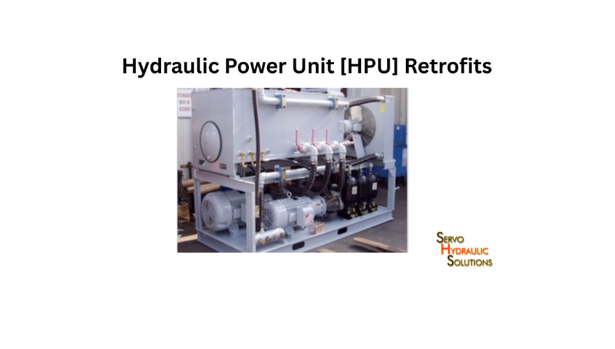
Multi-Station Legacy Hydraulic Power Unit (HPU) Retrofits: Adding VFD Controls, Manifolds & Smart Interlocks
November 20, 2026
Existing servo hydraulic test systems can often be kept productive through planned maintenance, timely repairs and targeted component replacement rather than a complete machine replacement. The right decision depends on the condition of the hydraulic power unit, servo valves, actuators, feedback sensors and control electronics, along with the reliability the laboratory needs.
For a testing laboratory, an unexpected breakdown is more than a maintenance problem. It can delay scheduled experiments, interrupt research work and leave valuable equipment unavailable for days. A practical maintenance programme helps identify developing faults early, while a clear repair-versus-rebuild assessment prevents money being spent on the wrong solution.
This guide covers existing servo hydraulic maintenance and repair, field inspections, remote diagnostics, common faults and the conditions that indicate whether a system should be repaired, rebuilt or replaced.
Why Servo Hydraulic Maintenance Matters
Servo hydraulic systems operate under demanding conditions. They may run for long test cycles, handle heavy specimens and produce repeated dynamic movements. Small issues such as contaminated oil, loose electrical connections or unstable feedback can gradually affect performance.
Maintenance is not simply about preventing leaks. It is about keeping the complete hydraulic and control system working together.
How Servo Hydraulic Test Stands Work
A servo hydraulic test stand uses pressurised hydraulic fluid to move an actuator according to commands from a control system.
A typical arrangement includes:
- Hydraulic power unit (HPU): Supplies pressurised oil at the required flow and pressure.
- Servo valve: Controls hydraulic flow to the actuator.
- Actuator or cylinder: Produces the required force and movement.
- Controller: Compares the commanded response with measured feedback.
- Sensors: Measure position, force, pressure or acceleration.
- Signal conditioning and amplifiers: Process sensor signals and provide the required electrical drive to control hardware.
- Safety circuits: Protect operators and equipment during abnormal conditions.
In a closed-loop test, the controller compares the commanded movement or force with the actual response. It then adjusts the servo valve output to reduce the difference.
This is why a fault in one component can affect the entire machine. A faulty LVDT, for example, may create a position error even when the actuator and hydraulic supply are mechanically sound.
Common Causes of Test Lab Downtime
Several problems repeatedly interrupt servo hydraulic testing:
- Hydraulic oil contamination or deterioration.
- Blocked or overdue filters.
- Servo valve sticking or unstable response.
- Hydraulic leaks and damaged seals.
- Actuator wear or internal leakage.
- Incorrect sensor feedback or electrical noise.
- Cooling system problems.
- Loose connectors or damaged cables.
- Controller faults and communication failures.
- Inadequate preventive maintenance.
Some faults appear suddenly, but the underlying cause may have developed over months. A gradual increase in oil temperature, for instance, can indicate a cooling problem, excessive internal leakage or another source of hydraulic inefficiency.
Benefits of Preventive Maintenance
A planned maintenance programme helps laboratories identify issues before they become major failures.
Its main benefits include:
- Reduced unplanned downtime: Early attention to developing faults can prevent longer interruptions.
- More consistent test performance: Stable hydraulic pressure and reliable feedback support repeatable operation.
- Longer component life: Correct oil condition, filtration and operating practices help protect pumps, valves and actuators.
- Better spare-parts planning: Maintenance records reveal which components are wearing out or becoming difficult to source.
- Safer operation: Regular checks help identify leaks, damaged hoses and defective safety devices.
- Better maintenance budgets: Planned work is generally easier to schedule and assess than emergency repairs.
Maintenance intervals should follow equipment manufacturer recommendations, operating conditions and actual system history. A heavily used shake table may need more frequent inspections than a test stand used occasionally.
When to Schedule Servo Hydraulic Service
Arrange an inspection when the system shows changes such as:
- Unusual pump or valve noise.
- Increasing oil temperature.
- Slower actuator movement.
- Repeated pressure fluctuations.
- Position or force control errors.
- Unexpected drift during a hold period.
- Frequent alarms or controller trips.
- Visible leakage around hoses, fittings or cylinders.
Service is also advisable after extended shutdowns, major component replacement, suspected oil contamination or a significant change in test performance.
Do not wait for a complete failure if the machine is already showing repeated warning signs.
Field Servo Hydraulic Service Checklist
A field inspection should cover the complete system, not just the component responsible for the latest alarm. The following checklist provides a practical starting point for a service visit.
Hydraulic Power Unit Inspection
The hydraulic power unit supplies the hydraulic energy needed by the test system. Its condition has a direct effect on actuator performance.
Inspect:
- Oil level and visible oil condition.
- Filter condition and differential pressure indicators, where fitted.
- Pump noise, vibration and signs of leakage.
- Pressure stability during operation.
- Oil temperature and cooling performance.
- Reservoir breather and ventilation.
- Hydraulic hoses, fittings and connections.
- Accumulator condition and associated safety arrangements.
Oil appearance alone cannot confirm cleanliness. Where contamination is suspected, use an appropriate oil sampling and analysis procedure.
Servo Valve and Amplifier Checks
Servo valves are sensitive components. Contamination, wear and incorrect electrical drive can affect their response.
Check:
- Valve body and mounting connections.
- Electrical connectors and cable condition.
- Evidence of leakage around the valve assembly.
- Amplifier power supply and status indicators.
- Command signal and feedback signal integrity.
- Valve response under an approved test procedure.
- Grounding, shielding and electrical noise.
For systems using older analogue valve drivers, confirm that the output characteristics remain suitable for the installed valve. Do not substitute an amplifier based only on connector appearance or nominal supply voltage.
Actuator and Cylinder Inspection
The actuator converts hydraulic pressure into mechanical movement. Wear or internal leakage can affect performance even when there is no obvious external leak.
Inspect:
- Rod surface and signs of scoring.
- Seal areas and external leakage.
- Mounting bolts and mechanical connections.
- Clevises, bearings and alignment.
- Unusual movement or mechanical noise.
- Position response and repeatability.
- Evidence of internal leakage, where suitable tests are available.
If the actuator moves unevenly or cannot maintain position, investigate both the hydraulic circuit and the mechanical load before deciding that a rebuild is necessary.
Sensor and Feedback Checks
Feedback faults can look like hydraulic problems. A controller may report position error because the sensor signal is incorrect, not because the actuator has failed.
Check:
- LVDT and other transducer connections.
- Cable condition and connector security.
- Sensor excitation and signal levels.
- Feedback polarity and scaling.
- Zero position and measurement range.
- Electrical noise or intermittent readings.
- Calibration status and available certificates.
For an LVDT, confirm that the signal conditioner is suitable for the sensor’s excitation and output arrangement. Incorrect wiring or scaling can produce misleading position readings.
Controller and Software Checks
The controller should be checked for hardware, configuration and communication issues.
Review:
- Active alarms and fault history.
- Input and output channel status.
- Controller communication.
- Software configuration and backup availability.
- Control mode and operating limits.
- Sensor scaling and engineering units.
- Changes made since the last successful test.
Do not change control gains or other critical parameters simply to clear an alarm. First identify the cause and follow the equipment’s approved commissioning procedure.
Safety Circuit and Emergency Stop Checks
Safety functions should be included in every suitable service inspection.
Check emergency-stop devices, travel limits, guards, pressure protection and other installed interlocks. Verify that safety circuits respond as intended using an approved test procedure.
Never bypass a safety device to keep testing. Any fault affecting an emergency stop, pressure protection or movement limit should be addressed before the machine returns to service.
Documentation and Service Records
A service visit should leave the laboratory with more than a verbal explanation.
Record:
- Equipment identification and operating hours, where available.
- Reported symptoms and fault history.
- Inspection findings.
- Measurements taken during service.
- Components repaired or replaced.
- Oil and filter maintenance.
- Controller or software changes.
- Safety checks completed.
- Outstanding recommendations.
- Date and details of the next inspection.
Good documentation helps distinguish recurring problems from unrelated faults and supports future repair-versus-rebuild decisions.
Remote Diagnostic Troubleshooting for Shake Tables
Not every servo hydraulic problem requires an immediate site visit. Remote diagnostics can help identify software, configuration, communication and some electrical issues before a technician travels to the laboratory.
It is especially useful when a shake table is unavailable and the laboratory needs to understand the likely cause quickly.
What Is Remote Diagnostic Troubleshooting?
Remote diagnostic troubleshooting uses information shared by the laboratory to assess a fault from another location.
Depending on the system and available access, a service engineer may review:
- Controller alarm logs.
- Software screenshots.
- Hydraulic pressure and temperature readings.
- Sensor feedback trends.
- DAQ recordings.
- Electrical drawings and wiring details.
- Recent maintenance or configuration changes.
Remote support may involve a secure connection to the control computer, but access should be authorised and managed under the laboratory’s IT and safety procedures.
When Remote Support Is Suitable
Remote support is useful for problems such as:
- Controller communication errors.
- Software configuration issues.
- Incorrect channel assignments.
- Sensor scaling questions.
- Repeated alarms with available diagnostic logs.
- Test sequence or data-recording problems.
- Basic signal troubleshooting.
For example, suppose a shake table reports a position error after a software configuration change. Reviewing the LVDT channel assignment, feedback scaling and alarm history remotely may help identify a configuration issue before any hardware is replaced.
Information to Share Before Remote Support
A clear fault report saves time. Before contacting the service team, collect:
- Equipment manufacturer, model and identification details.
- Controller and software versions.
- Exact alarm message or fault code.
- When the problem started.
- Whether it occurs at startup, during movement or under load.
- Recent maintenance or component changes.
- Available pressure and temperature readings.
- Relevant sensor trends or DAQ recordings.
- Photographs of the affected components, where safe to obtain.
- Electrical and hydraulic drawings.
Share only the information required for diagnosis, using an approved secure method. Do not expose control computers to unauthorised remote access.
Common Remote Diagnostic Checks
A service engineer may review the following:
| Area | Remote diagnostic check |
| Controller | Alarm history, status and communication |
| Feedback | LVDT readings, scaling and signal stability |
| DAQ | Recorded channels, noise and timing |
| Hydraulic system | Pressure and temperature readings |
| Servo amplifier | Status indicators and available command information |
| Software | Configuration, test sequence and recent changes |
| Network | Communication status and authorised connection settings |
Remote diagnosis can narrow down the likely cause, but it cannot confirm every mechanical or hydraulic condition.
When On-Site Field Service Is Needed
An on-site visit is normally required when the fault involves physical inspection, hydraulic measurements or component work.
Examples include:
- Significant hydraulic leakage.
- Suspected pump or actuator damage.
- Contaminated hydraulic oil requiring corrective work.
- Servo valve removal or replacement.
- Damaged hoses or fittings.
- Mechanical alignment problems.
- Pressure or flow measurements requiring specialist equipment.
- Safety-system faults requiring physical verification.
If a fault creates a risk to people or equipment, stop operation and follow the laboratory’s safety procedure. Remote support should not be used as a reason to continue operating an unsafe machine.
How Remote Support Reduces Downtime
Remote support can shorten the initial diagnosis stage. It may help the laboratory identify the likely replacement part, prepare access to the machine and arrange the correct tools before a technician arrives.
It can also prevent unnecessary component replacement. A feedback scaling issue, for example, should not automatically lead to the purchase of a new actuator.
The most effective approach is often a combination: remote assessment first, followed by field service when physical intervention is required.
Common Servo Hydraulic Faults
The symptoms below are useful starting points for troubleshooting. They are not definitive diagnoses. Several faults can produce similar symptoms, so checks should be performed systematically.
Low or No System Pressure
Possible causes include:
- Pump or motor failure.
- Incorrect relief valve setting.
- Low reservoir oil level.
- Suction-side restriction or air ingress.
- Faulty pressure control components.
- Major internal or external leakage.
Check pressure using suitable instruments and approved procedures. Do not adjust relief valves without understanding the system’s specified operating limits.
Slow or Weak Actuator Movement
Possible causes include insufficient flow, low system pressure, a restricted filter, internal actuator leakage or incorrect servo valve operation.
Compare actual pressure and movement with the system’s expected operating conditions. Also check whether the problem occurs under all loads or only during demanding test sequences.
Actuator Drift or Position Error
Drift may result from internal leakage, valve leakage, mechanical loading, incorrect feedback scaling or an unstable control signal.
First determine whether the actuator is physically moving or whether the displayed position is changing because of a sensor problem. Comparing independent measurements, where available, can help separate the two.
Hydraulic Leakage
Leaks may occur at hose connections, seals, fittings, manifolds or actuator rod seals.
Identify the source and assess the severity before deciding on repair. Never use hands to search for a high-pressure hydraulic leak. A fine jet of hydraulic fluid can penetrate skin and cause a serious injection injury.
Isolate and depressurise the system using the approved procedure before carrying out repair work.
Excessive Noise or Vibration
Possible causes include cavitation, aeration, pump wear, loose mounting hardware, misalignment or mechanical resonance.
Note when the noise occurs: at startup, during actuator movement, under load or continuously. This information can help narrow down the source.
Overheating Hydraulic Oil
Oil temperature may rise because of inadequate cooling, excessive internal leakage, continuous operation at high pressure or unsuitable system settings.
Check cooling performance, oil condition, filter restrictions and operating history. Repeated overheating should be investigated rather than managed simply by reducing test time.
Erratic Control Response
Unstable movement or oscillation can result from feedback noise, incorrect control settings, valve problems, mechanical looseness or hydraulic instability.
Check sensor signals and mechanical condition before changing controller parameters. Adjustments to control gains should be made only by qualified personnel following a controlled procedure.
Servo Valve Faults
Servo valve problems may include contamination, sticking, electrical faults, wear or unstable response.
Possible indicators are inconsistent actuator movement, unexpected pressure behaviour and poor response to command signals.
A valve should be tested using suitable equipment and the manufacturer’s recommended procedure. Cleaning or replacing it without identifying the cause of contamination may lead to a repeat failure.
Sensor and Feedback Faults
A faulty LVDT, load cell or pressure transducer can produce incorrect measurements and control errors.
Check the sensor, cable, connector, excitation supply, signal conditioner and controller input. Confirm polarity, scaling and calibration status before replacing hardware.
Servo Hydraulic Repair vs Rebuild
The decision to repair or rebuild should be based on the condition of the equipment, the fault’s cause, component availability and the expected service life after the work.
A small, isolated failure does not normally justify a complete rebuild. On the other hand, repeated failures across several major components may make another individual repair poor value.
What Is a Servo Hydraulic Repair?
A repair addresses a specific fault or damaged component while retaining the rest of the system.
Examples include:
- Replacing a damaged hydraulic hose.
- Repairing an external leak.
- Replacing a faulty sensor or connector.
- Servicing a pump or valve when appropriate.
- Replacing a defective signal conditioner.
- Correcting a wiring or communication fault.
- Replacing worn seals where the component remains serviceable.
The aim is to restore the affected function without unnecessarily disturbing healthy equipment.
What Is a Servo Hydraulic Rebuild?
A rebuild is a broader restoration of a component or system. It may involve dismantling, inspecting, measuring, replacing worn parts and restoring the equipment to defined performance requirements.
Depending on the scope, a rebuild may include:
- Pump inspection and overhaul.
- Actuator or cylinder rebuilding.
- Servo valve refurbishment.
- Replacement of seals and bearings.
- Hydraulic flushing and filtration work.
- Electrical and control-system restoration.
- Verification and recommissioning.
A rebuild should have a documented scope and acceptance criteria. The word itself does not guarantee that every component has been restored to its original specification.
Repair vs Rebuild Comparison
| Factor | Repair | Rebuild |
| Scope | Specific fault or component | Wider component or system restoration |
| Work involved | Targeted replacement or correction | Inspection, dismantling and broader restoration |
| Downtime | Often shorter | Usually longer |
| Initial cost | Often lower | Usually higher |
| Best suited to | Isolated, well-understood faults | Widespread wear or recurring failures |
| Performance outcome | Restores the affected function | Aims to restore broader system condition |
| Risk | Other ageing parts may still fail | Hidden issues may appear during dismantling |
Actual cost and downtime depend on the machine, parts availability and work required.
When Repair Is the Better Option
Repair is usually appropriate when:
- The fault is clearly identified.
- Most of the system remains in good condition.
- The affected component can be serviced reliably.
- Replacement parts are available.
- The machine continues to meet its testing requirements.
- The expected remaining service life justifies the cost.
For example, if a test stand has stable pressure, good actuator condition and a single damaged feedback cable, replacing the cable and verifying the signal is more sensible than rebuilding the hydraulic system.
When Rebuild Is the Better Option
Consider a rebuild when:
- Several major components show significant wear.
- The same faults keep returning.
- Internal leakage is affecting performance.
- The pump or actuator has deteriorated.
- A component has reached the point where individual repairs are no longer dependable.
- The laboratory needs a more predictable period of future operation.
A rebuild may also be suitable during a planned shutdown when multiple maintenance tasks can be completed together.
When Replacement Is the Better Option
Replacement becomes worth considering when the system is structurally damaged, critical components cannot be sourced, performance requirements cannot be met or the cost and risk of rebuilding approach those of a suitable replacement.
Also consider whether the existing controller, hydraulic power unit and mechanical structure can support the laboratory’s future testing requirements.
The decision should compare the complete lifecycle cost, not just the purchase price. Include installation, foundation or facility changes, commissioning, training, calibration and future maintenance.
How to Minimize Test Lab Downtime
Minimizing downtime requires a combination of maintenance planning, spare-parts management, accurate fault records and timely service support.
Plan Maintenance Before Failure
Use manufacturer recommendations and operating history to establish inspection intervals.
Schedule oil sampling, filter replacement, hose inspections and component checks around the laboratory’s testing calendar where practical.
Do not rely only on fixed calendar intervals. Operating hours, test intensity, oil condition and the number of dynamic cycles can all affect maintenance needs.
Keep Critical Spare Parts Available
Identify components that could stop the entire test stand if they fail.
Depending on the equipment, these may include:
- Hydraulic filters and seals.
- Common hoses and fittings.
- Sensor cables and connectors.
- Pressure transducers.
- LVDTs or suitable replacement sensors.
- Servo valve amplifiers.
- Signal conditioners.
- Electrical protection and control components.
Maintain a spare-parts register with part numbers, specifications, supplier details and compatibility notes. Avoid buying replacement electronics based only on similar appearance.
Use Remote Diagnostics First
For suitable faults, remote troubleshooting can help establish whether the issue is software-related, electrical, hydraulic or mechanical.
Prepare alarm logs, readings and drawings before contacting support. A clear description of the fault is more useful than a general statement that the machine is not working.
Schedule Field Service at the Right Time
Plan on-site maintenance during scheduled shutdowns or between major test programmes whenever possible.
If several components need attention, group the work into one service visit where practical. This can reduce repeated travel and interruptions.
However, safety-critical failures should be addressed immediately rather than postponed for scheduling convenience.
Document Recurring Faults
Maintain a fault log that includes symptoms, dates, operating conditions, actions taken and the final diagnosis.
A repeated pressure alarm, for example, may have a different underlying cause each time. Historical records help determine whether the problem is linked to oil temperature, a particular operating mode or a component that is gradually deteriorating.
Plan Phased Maintenance or Upgrades
Not every ageing test stand needs a complete overhaul at once.
A phased approach may address the most urgent reliability issues first:
- Restore hydraulic cleanliness and resolve leaks.
- Repair or replace unreliable sensors and feedback components.
- Service worn pumps, valves or actuators.
- Address controller and DAQ obsolescence, including upgrading legacy hydraulic actuator test stands with COTS parts when key electronics are discontinued..
- Complete broader rebuilds or upgrades where justified.
Each phase should have clear acceptance checks. This approach helps laboratories manage budgets while avoiding a collection of unrelated changes that are difficult to commission.
Conclusion
Reliable servo hydraulic equipment depends on more than replacing failed parts. Hydraulic cleanliness, valve performance, actuator condition, sensor feedback, controller configuration and safety systems all contribute to dependable testing.
Existing servo hydraulic maintenance and repair is often the most practical starting point when faults are isolated and the rest of the system remains serviceable. A rebuild is more appropriate when wear and recurring failures affect several major components. Replacement should be considered when the equipment can no longer meet technical, safety or lifecycle requirements.
A consistent field service checklist, useful fault records and remote diagnostic support can help laboratories identify problems earlier and reduce avoidable downtime. To discuss servo-hydraulic services or broader testing systems, reach out to our engineering team.
FAQs
1. What is existing servo hydraulic maintenance and repair?
It involves inspecting, servicing, troubleshooting and repairing installed servo hydraulic equipment, including hydraulic power units, servo valves, actuators, sensors and controllers. The aim is to maintain reliable operation and restore performance when faults occur.
2. What is a field servo hydraulic service checklist?
It is a structured list of inspection and verification tasks performed during an on-site service visit. It typically covers hydraulic pressure, oil condition, filters, valves, actuators, feedback sensors, controller operation, safety circuits and service documentation.
3. What is remote diagnostic troubleshooting for shake tables?
It is the process of investigating shake table faults using information such as alarm logs, controller status, sensor readings, DAQ recordings and system documentation. It can help identify software, communication and some electrical issues before an on-site visit is arranged.
4. What is the difference between servo hydraulic repair and rebuild?
A repair addresses a specific fault or component, while a rebuild involves wider inspection and restoration of a component or system. Repair is generally suitable for isolated problems; rebuilding is more appropriate when wear or recurring faults are widespread.
5. When should I repair a servo hydraulic test stand?
Repair is appropriate when the fault is identifiable, the remaining equipment is in good condition and the required parts are available. It is often the practical choice for isolated leaks, faulty sensors, damaged cables or individual component failures.
6. When should I rebuild a servo hydraulic test stand?
Consider rebuilding when several major components show wear, repeated repairs are becoming unreliable or internal leakage and performance deterioration affect operation. A rebuild should include a defined scope and measurable acceptance criteria.
7. When should I replace a servo hydraulic test stand?
Replacement may be justified when critical parts are unavailable, the system cannot meet required performance or safety conditions, or the cost and risk of restoration are no longer reasonable. Compare the full lifecycle cost of replacement with the cost of repair and rebuilding before deciding.
Experiencing Test Stand Faults, Leaks, or Unplanned Downtime?
Schedule remote diagnostic troubleshooting, on-site field inspections, or a practical repair-versus-rebuild assessment to keep your servo-hydraulic equipment running reliably.