- Have any Query
- (303) 807-1061
- doug@servohydraulicsolutions.com

Phased Lab Expansion: How to Specify a Uniaxial Shake Table Today That Upgrades to Biaxial Testing Later

Public Education & Museum Earthquake Simulators: Safety Interlocks, Payload Limits & Cost-Effective COTS Builds
November 19, 2026
Custom High-Force Shaker Tables vs Standard Off-the-Shelf Platforms: When Bespoke Engineering Pays Off
November 19, 2026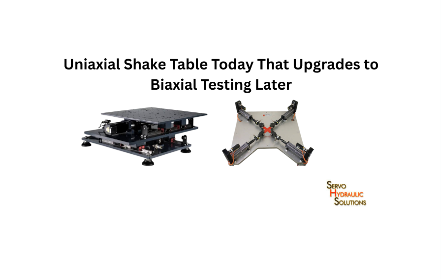
A laboratory can start with a uniaxial shake table and expand to biaxial testing later, but only if the original system is designed with that upgrade in mind. The key is to plan the mechanical structure, foundations, actuator arrangement, hydraulic supply, controller, and available space around both present and future testing requirements.
For universities and structural dynamics laboratories working with limited initial budgets, a modular shake table system can make phased expansion practical. Instead of purchasing every component at once, the lab can install a suitable uniaxial system today while preparing the facility for a second horizontal axis when research needs and funding increase.
The key distinction is between a genuinely upgradeable system and one with enough space around it. A successful upgrade requires engineering decisions long before the second actuator arrives.
What Is a Modular Shake Table System?
A modular shake table system is a seismic testing platform designed with separate mechanical, hydraulic, electrical, and control components that can be configured or expanded as laboratory requirements change.
Rather than treating the table as one permanently fixed assembly, the design considers how additional actuators, fixtures, control channels, and supporting equipment could be integrated later.
For example, a university may initially need horizontal earthquake simulation along one axis to study structural frames or equipment response. A few years later, its researchers may want to investigate how specimens behave under simultaneous horizontal excitation in two directions. A modular design can make that transition easier if the original equipment was specified for the additional demands.
How a Modular Shake Table Works
A typical modular system includes:
- Shake table platform: The moving surface on which test specimens and fixtures are mounted.
- Actuator assembly: Produces controlled motion along the required axis or axes.
- Hydraulic power unit: Supplies pressurised fluid to operate servo-hydraulic actuators.
- Servo valves and manifolds: Regulate hydraulic flow and actuator movement.
- Digital controller: Generates and controls the commanded motion.
- Sensors and data acquisition: Measure displacement, acceleration, force, pressure, and specimen response.
- Foundation and reaction structure: Transfer dynamic forces into the supporting laboratory structure.
In a phased design, these elements are reviewed as part of a future system configuration. The table might initially operate with one actuator, while the foundation, mounting interfaces, and control architecture are prepared for a second actuator.
That does not mean every component must be installed immediately. It means the first installation should not prevent the second stage from being completed safely.
Difference Between Modular and Fixed Shake Table Design
A fixed shake table is generally designed around a defined operating configuration. It can perform its intended tests effectively, but substantial changes may require new mechanical or facility work.
A modular system considers future changes during the initial engineering stage.
| Design consideration | Fixed shake table | Modular shake table |
| Initial configuration | Defined operating arrangement | Planned around present and future configurations |
| Mechanical interfaces | May be application-specific | Can include reserved expansion interfaces |
| Additional actuators | May require significant redesign | Can be accommodated if designed for them |
| Control channels | Sized for current requirements | May include expansion capacity |
| Facility planning | Based mainly on current installation | Considers future equipment and access |
| Initial investment | Depends on the selected configuration | May include additional preparation costs |
| Expansion | Can be difficult or expensive | Potentially easier with proper engineering |
Modular does not automatically mean cheaper, faster, or more capable. The value comes from reducing avoidable redesign when the laboratory’s requirements change.
When a Modular System Is Worth Considering
A modular approach is worth considering when:
- A university expects to introduce more advanced seismic research over time.
- Funding is available for a basic system now, but not a complete biaxial installation.
- Researchers currently perform single-axis testing but anticipate multi-directional studies.
- The laboratory expects to test larger or more complex specimens in the future.
- The facility is being constructed or renovated, and foundation decisions must be made early.
It is particularly useful when the laboratory has a clear expansion plan. If future biaxial testing is only a vague possibility, the extra cost of preparing for it should be compared against the cost of purchasing a separate system later.
Why Upgrade From Uniaxial to Biaxial Testing?
Uniaxial testing is useful for studying how structures and equipment respond to motion in one horizontal direction. Biaxial testing adds a second horizontal direction, allowing researchers to investigate the combined effects of two perpendicular motion components.
The need for an upgrade usually develops when the research question becomes more demanding. A specimen that performs well under one-directional movement may respond differently when horizontal forces act along two axes.
What Is a Uniaxial Shake Table?
A uniaxial shake table produces controlled movement along one primary axis. The platform moves horizontally, usually through a servo-hydraulic actuator or another suitable drive arrangement.
It is commonly used for:
- Undergraduate and postgraduate laboratory demonstrations.
- Structural model testing.
- Component and equipment vibration studies.
- Single-direction earthquake simulation.
- Research into basic dynamic response.
- Testing control algorithms and instrumentation.
Its relatively straightforward configuration can make it suitable for laboratories beginning seismic testing.
However, a uniaxial table cannot reproduce simultaneous independent horizontal movement in two perpendicular directions. Rotating a specimen between separate tests does not replicate applying two components at the same time.
What Is a Biaxial Shake Table?
A biaxial shake table produces controlled horizontal movement along two perpendicular axes, commonly identified as X and Y.
Both axes can operate simultaneously, allowing the specimen to experience combined horizontal excitation.
This arrangement is useful for studying:
- Structural response under two-directional earthquake motion.
- Equipment and component stability.
- Torsional response caused by asymmetric mass or stiffness.
- Connections and supports exposed to combined horizontal forces.
- Interaction between structural movement in perpendicular directions.
A biaxial system needs more than a second actuator. Its platform, guides, bearings, reaction structure, hydraulic supply, and controller must all support the intended two-axis movement.
When Biaxial Testing Becomes Necessary
Biaxial testing becomes important when a research objective cannot be represented adequately by one-directional excitation.
Consider a laboratory testing a small structural frame. Under uniaxial movement, researchers may measure lateral displacement, acceleration, and connection behaviour along one direction.
Now imagine the same frame is exposed to simultaneous X- and Y-axis excitation. Its columns, joints, and supports may experience a different combination of forces and deformation. The additional movement can reveal behaviour that a single-axis test would not capture.
Biaxial testing may be justified when:
- The research involves simultaneous horizontal earthquake components.
- Specimen geometry or stiffness varies significantly between directions.
- Torsional or coupled response is important.
- Equipment is installed with different support conditions along two axes.
- A testing programme specifically requires two-directional excitation.
Not every project needs biaxial capability. The correct choice depends on the specimen, test objective, excitation requirements, and applicable testing procedure.
Benefits of Phased Lab Expansion
A phased approach lets a laboratory spread investment across stages.
Its main benefits include:
- Lower initial equipment commitment: The lab purchases the uniaxial configuration needed for its current research.
- Planned technical development: Researchers can begin with simpler tests and expand their capabilities as projects develop.
- Better use of facility resources: Foundation and utility preparation can be coordinated with the initial installation.
- Reduced avoidable redesign: Reserved interfaces and adequate capacity can prevent major changes during expansion.
- Flexible research planning: The lab can introduce additional test programmes without automatically replacing its entire installation.
The main caution is that phased expansion only works when the future configuration is defined early enough to influence the original design.
Upgradeable Uniaxial to Biaxial Shake Table
An upgradeable uniaxial-to-biaxial shake table is not simply a standard uniaxial system with an extra actuator added later. Its original design accounts for the mechanical, hydraulic, structural, and control requirements of future two-axis operation.
This distinction matters. A second actuator can introduce new forces, constraints, movement interactions, and control requirements that the original installation may not have been designed to handle.
What Can Be Upgraded Later?
Depending on the original design, several components may be added or expanded:
- A second servo-hydraulic actuator.
- Additional servo valves and hydraulic manifolds.
- Extra controller channels and drive electronics.
- Additional displacement, acceleration, and force sensors.
- Expanded data acquisition capacity.
- Updated test-control software and operating configurations.
- Additional safety interlocks and monitoring equipment.
Some fixtures and instrumentation may also be reused if their ratings and mounting arrangements suit the expanded system.
The important point is to confirm compatibility before buying the original equipment. A spare controller channel is useful only if the controller hardware, software, and real-time control architecture can support the additional axis.
What Cannot Be Easily Upgraded?
Certain elements are expensive or difficult to modify after installation.
Foundation and reaction structure: The second axis changes the load paths and may introduce forces that the original foundation was not designed to resist.
Table platform: The existing platform may lack the stiffness, mounting interfaces, or geometry required for two-axis movement.
Guidance and bearing arrangement: The mechanical system must permit the required motion while controlling unwanted movement and maintaining alignment.
Hydraulic power capacity: The existing hydraulic supply may not provide sufficient flow and pressure for simultaneous actuator operation.
Operating envelope: Adding an actuator does not automatically preserve the original payload, acceleration, velocity, stroke, or frequency performance.
Assess these items during the first design review, not after the laboratory has already installed its equipment.
Design the Table for Future Expansion
Start with a written description of the future biaxial configuration.
The specification should identify:
- Expected specimen mass and dimensions.
- Required X- and Y-axis displacement.
- Peak velocity and acceleration.
- Operating frequency range.
- Simultaneous actuator demand.
- Expected overturning moments.
- Table and fixture mass.
- Foundation and reaction loads.
- Required control and measurement channels.
The mechanical supplier should then explain how the initial uniaxial arrangement can be converted to the intended biaxial configuration.
Ask for drawings showing both stages. These should identify actuator positions, mounting interfaces, clearances, load paths, utility connections, and maintenance access.
A useful procurement requirement is a future-state design review. The supplier should demonstrate that the proposed first-stage installation fits within the defined second-stage operating envelope.
Avoid False Upgrade Claims
Be cautious when a supplier describes a system as upgradeable without providing engineering details.
Statements such as “biaxial-ready” or “future expansion possible” are not sufficient on their own.
Ask for written confirmation of:
- Which components will be reused.
- Which components must be replaced.
- Whether the foundation supports the future configuration.
- Whether the platform needs structural modification.
- Whether the hydraulic power unit requires additional capacity.
- Whether the controller can operate both axes simultaneously.
- What performance limits will apply after expansion.
A genuine upgrade path should be supported by drawings, calculations, component ratings, and a clear list of future work.
When a New Biaxial Table Is Better
A new biaxial table may be more practical when the original uniaxial equipment was not designed for additional loads or movement.
It may also make sense when:
- The existing platform is too small for future specimens.
- The foundation cannot accommodate the new reaction forces.
- The hydraulic supply is already operating near its limits.
- The second actuator cannot be integrated without extensive redesign.
- The laboratory requires a substantially different payload or frequency range.
Compare the full retrofit cost with the cost of a new system. Include engineering, civil work, equipment downtime, installation, commissioning, and performance validation. The lowest initial purchase price does not always produce the lowest long-term cost.
Scalable COTS Earthquake Simulator Design
A scalable COTS earthquake simulator design combines commercially available components with engineering that allows the system to grow as testing requirements increase.
COTS means commercially available off-the-shelf. These components can reduce the need to manufacture every part from scratch, but the complete shake table still requires careful system integration.
What Is a COTS Earthquake Simulator?
A COTS earthquake simulator uses commercially available equipment such as:
- Servo-hydraulic actuators.
- Servo valves.
- Hydraulic pumps and power units.
- Industrial controllers.
- Sensors and transducers.
- Data acquisition hardware.
- Hydraulic filters, manifolds, and fittings.
- Safety and monitoring components.
The components are selected and integrated to produce controlled seismic motion.
A COTS-based system can still be engineered for a specific laboratory. Off-the-shelf does not mean that the equipment is selected without considering the payload, motion requirements, structural loads, or control performance.
Benefits of COTS Components
COTS components can offer several practical advantages.
Availability: Standard components may be easier to source than specially manufactured alternatives, depending on the supplier and region.
Serviceability: Common equipment can be easier for maintenance teams to identify, inspect, and replace.
Technical documentation: Manufacturers generally provide component specifications, operating limits, and maintenance information.
Expansion options: Additional compatible sensors, valves, controllers, and hydraulic equipment may be available when the system grows.
Reduced development effort: Proven components can reduce the custom manufacturing required.
For a university planning phased seismic testing lab expansion, these advantages can make procurement and maintenance more manageable.
Limitations of COTS Systems
A commercially available actuator or controller is not automatically suitable for a particular shake table.
Common limitations include:
- Insufficient force or stroke for the intended specimen.
- Flow limitations during simultaneous actuator operation.
- Control bandwidth that does not meet the test requirements.
- Mechanical interfaces that do not match the platform.
- Communication or synchronisation limitations.
- Inadequate protection against operating faults.
- Compatibility issues between equipment from different manufacturers.
The complete system must be evaluated under the intended operating conditions.
When Custom Engineering Is Still Needed
Custom engineering is usually necessary for the table structure, foundation, actuator mounting, reaction frame, guidance arrangement, and system integration.
A laboratory may use standard actuators and servo valves but still need a purpose-designed platform that can resist dynamic loading without excessive deformation.
The controller configuration also needs attention. Two axes operating simultaneously require suitable coordination, feedback, safety logic, and test-command management.
How to Balance COTS and Custom Design
A practical approach is to use standard components where their ratings and performance match the application, while custom-engineering the parts that determine overall system behaviour.
For example, a laboratory may select commercially available servo-hydraulic actuators and a digital controller, then design a custom table platform and mounting arrangement around its specimen requirements.
The supplier should provide a compatibility review covering:
- Force, stroke, velocity, and frequency.
- Hydraulic pressure and flow.
- Mechanical mounting and alignment.
- Controller and sensor interfaces.
- Safety functions.
- Future expansion requirements.
This combination can create a scalable system without forcing the laboratory to purchase an entirely bespoke installation.
Future-Proofing Structural Dynamics Labs
Future-proofing structural dynamics labs means making current equipment and facility decisions with realistic future research needs in mind. It does not mean designing for every possible test. It means identifying likely changes and avoiding decisions that unnecessarily restrict expansion.
Plan for Future Specimens and Test Types
List the specimens the laboratory expects to test over the next several years.
A small structural model, a heavy equipment cabinet, and a large component may have very different requirements.
Consider:
- Maximum specimen mass.
- Specimen height and centre of gravity.
- Mounting footprint.
- Fixture weight.
- Expected acceleration and displacement.
- Test frequency range.
- Required motion directions.
Select the table around the actual test envelope rather than a single maximum payload figure.
Reserve Space for Additional Actuators
A second actuator needs more than a mounting point. It needs physical clearance, installation access, hydraulic connections, cable routing, and maintenance space.
The facility layout should account for:
- Actuator body dimensions.
- Rod and clevis movement.
- Mounting brackets.
- Hydraulic hoses and manifolds.
- Sensor wiring.
- Maintenance access.
- Specimen installation and removal.
A layout drawing should show both the first-stage and expanded configurations. This helps prevent situations where laboratory walls, equipment cabinets, or access routes obstruct future installation.
Design Foundations for Higher Loads
The foundation should be assessed for the future system, including its dynamic loads and reaction forces.
A preliminary inertial-force estimate is:
[
F=ma
]
Where:
- (F) = inertial force.
- (m) = moving mass.
- (a) = acceleration.
For example, a moving mass of 5,000 kg subjected to an acceleration of (2,m/s^2) produces a preliminary inertial-force estimate of 10,000 N.
This is not a foundation design calculation. Actual foundation requirements depend on dynamic response, actuator forces, reaction loads, structural stiffness, anchorage, vibration transmission, and other design factors.
If biaxial operation is planned, the engineer must evaluate the combined loading and load paths in both horizontal directions.
Plan Hydraulic Supply and Control Capacity
Hydraulic power is one of the most important considerations in a future upgrade.
The second actuator may increase peak and continuous flow demand, particularly when both axes operate simultaneously.
The specification should cover:
- Required operating pressure.
- Continuous and peak flow.
- Simultaneous actuator demand.
- Accumulator capacity, where applicable.
- Cooling and filtration.
- Hydraulic piping and manifold capacity.
- Emergency shutdown arrangements.
Do not assume that the existing hydraulic power unit can support another actuator simply because it has unused connections.
Control capacity needs similar attention. Check the number of available control channels, real-time processing capability, feedback inputs, software licensing, and synchronised operation requirements.
Allow for Sensors and Data Acquisition Growth
A biaxial test may require more measurement channels than a uniaxial test.
The laboratory may need additional accelerometers, displacement transducers, force measurements, strain gauges, pressure sensors, and specimen-response instrumentation.
Plan for:
- Spare analogue and digital input channels.
- Suitable sampling rates.
- Synchronous data collection.
- Sensor power and signal conditioning.
- Cable routing and connectors.
- Data storage and processing capacity.
Good instrumentation planning avoids last-minute modifications that can delay commissioning.
Phased Seismic Testing Lab Expansion
A phased expansion works best when each stage has defined deliverables and acceptance criteria. The following approach provides a practical route from initial uniaxial testing to a validated biaxial configuration.
Phase 1: Specify the Uniaxial System
Begin with the tests the laboratory needs to perform immediately.
Define the required payload, platform dimensions, acceleration, displacement, velocity, frequency range, and control accuracy.
At this stage, also prepare the future biaxial requirements. The supplier should use them to assess the first-stage foundation, platform, hydraulic supply, and controller.
Phase 1 deliverables should include:
- Uniaxial system specifications.
- Future biaxial design requirements.
- Foundation and installation drawings.
- Reserved mechanical interfaces.
- Hydraulic and electrical capacity assessment.
- Initial acceptance-test requirements.
Phase 2: Prepare the Facility for Biaxial Expansion
Complete the facility work needed for the future configuration while the initial installation is being planned.
This may include foundation reinforcement, reserved actuator mounting locations, additional utility routes, electrical provisions, and equipment access.
It is often more efficient to carry out suitable civil work during the first installation than to reopen floors or modify an operating laboratory later.
However, any reserved foundation or mounting provision must be based on engineering calculations for the future configuration.
Phase 3: Add the Second Actuator and Controls
Once the laboratory has funding and a confirmed biaxial test programme, install the second actuator and the required supporting equipment.
This may involve:
- Second-axis actuator and mounting hardware.
- Additional servo valve and hydraulic connections.
- Controller and feedback-channel expansion.
- Additional sensors and data acquisition.
- Updated control software.
- Revised safety interlocks.
- Mechanical alignment and integration.
The existing system should be reviewed before installation. Confirm its condition, compatibility, and remaining operating capacity rather than assume them.
Phase 4: Commission and Validate Biaxial Testing
The expanded system must be commissioned as a complete two-axis installation.
Testing should verify:
- Actuator movement and alignment.
- Displacement and velocity performance.
- Force and hydraulic response.
- Cross-axis interaction.
- Synchronisation between axes.
- Sensor calibration and data quality.
- Emergency stops and safety functions.
- Performance under representative operating conditions.
Commissioning should progress from controlled, low-demand tests to more demanding operating conditions within the approved limits.
The supplier should document the final operating envelope, limitations, maintenance requirements, and acceptance results. The laboratory should not treat the system as ready for research until the required validation is complete.
How to Avoid Costly Retrofit Mistakes
Most retrofit problems begin with assumptions made during the original purchase.
Common mistakes include:
- Selecting a foundation based only on the first-stage actuator.
- Buying a table platform that cannot support future mechanical changes.
- Assuming the hydraulic power unit has enough spare capacity.
- Ignoring the additional controller and sensor channels.
- Failing to reserve space for installation and maintenance.
- Not defining the future specimen envelope.
- Accepting verbal upgrade promises without technical documentation.
The best safeguard is a written expansion specification, supported by drawings and calculations. Ask the supplier to identify what is included in the first purchase, what is reserved for later, and what additional work will be required.
How to Specify a Modular Shake Table System
A good specification describes what the laboratory needs to test, how the system should perform, and what must be possible during future expansion.
Avoid beginning with a product model or actuator size. Start with the research requirements.
Define Current and Future Test Requirements
Prepare two requirement lists: one for current uniaxial work and another for the intended biaxial configuration.
Include specimen mass, dimensions, centre of gravity, fixture weight, acceleration, displacement, velocity, frequency, waveform, and test duration.
For biaxial testing, state whether both axes must operate simultaneously and identify the required motion combinations.
This prevents the supplier from designing only for the first stage while treating future expansion as an undefined possibility.
Match Table Size, Payload, and Motion Limits
The table platform must accommodate the specimen, fixture, sensors, and mounting hardware.
Payload should be considered alongside acceleration, stroke, velocity, and frequency. A system may support a high static mass but have a lower dynamic operating capability under demanding motion conditions.
For sinusoidal motion, the relationship between peak displacement amplitude and peak acceleration is:
[
a_{\max}=(2\pi f)^2x
]
Where (f) is frequency in hertz and (x) is peak displacement amplitude in metres.
This relationship illustrates why displacement and frequency cannot be specified independently. As frequency increases, the acceleration required for the same displacement rises rapidly.
Always distinguish peak displacement from peak-to-peak stroke in supplier quotations.
Review Actuator and Hydraulic Capacity
Request actuator performance data covering force, stroke, velocity, and operating frequency.
The hydraulic review should include pressure, continuous flow, peak flow, cooling, filtration, and simultaneous operating demand.
For a future biaxial configuration, request calculations or documented capacity assessments for both actuators operating together. A system that performs well with one actuator may not maintain the same performance when the second axis is active.
Plan Controller and DAQ Expansion
Confirm that the controller can support the future number of axes, feedback channels, safety functions, and required control algorithms.
Also check:
- Software upgrade requirements.
- Additional hardware costs.
- Real-time synchronisation.
- Sensor compatibility.
- Data acquisition sampling rates.
- Calibration and testing requirements.
Ask whether future expansion requires replacing the controller or simply adding compatible hardware and licences—especially if your research roadmap could eventually expand toward more complex multi-axis testing platforms.
Compare Complete System Quotations
Compare suppliers using the same technical requirements.
A useful quotation comparison should separate:
| Quotation item | What to check |
| Mechanical system | Platform, guides, bearings, mounting interfaces |
| Actuators | Force, stroke, velocity, frequency |
| Hydraulic equipment | Pressure, flow, cooling, filtration |
| Controller | Axis capacity, feedback, software |
| Instrumentation | Sensors, signal conditioning, DAQ |
| Foundation | Design responsibility and civil work |
| Installation | Transport, assembly, alignment |
| Commissioning | Testing, calibration, acceptance criteria |
| Future upgrade | Reused parts, new components, additional work |
| Support | Training, maintenance, spare parts |
The lowest initial quote may exclude foundation preparation, control upgrades, commissioning, or future integration work. Compare the complete first-stage cost and the estimated cost of reaching the planned biaxial configuration.
Questions to Ask Before Buying
Before placing an order, ask the supplier:
- Is the proposed uniaxial table designed for a defined future biaxial configuration?
- Which mechanical components can be reused?
- Will the foundation support the future actuator arrangement and reaction loads?
- Can the table platform accommodate two-axis movement?
- What hydraulic pressure and flow will both actuators require simultaneously?
- Can the controller support the additional axis?
- How many spare sensor and DAQ channels are available?
- What modifications will be needed during expansion?
- Will the upgrade affect payload, acceleration, stroke, or frequency performance?
- Can the supplier provide drawings and a separate quotation for the future expansion?
Clear answers make it easier to distinguish a properly engineered modular shake table system from a standard uniaxial product with a loosely defined upgrade promise.
Conclusion
A phased approach to shake table procurement can help structural dynamics laboratories build testing capability without committing to a complete biaxial installation immediately. A uniaxial system is a sensible starting point when it meets current research requirements, but its future expansion must be considered during the original design.
The most important decisions involve the foundation, platform structure, actuator arrangement, hydraulic capacity, controller, instrumentation, and laboratory layout. These are the areas where an inexpensive first-stage decision can become an expensive retrofit later.
For a successful upgradeable uniaxial-to-biaxial shake table, ask the supplier to document the complete future configuration, identify reusable components, and confirm the expanded system’s performance limits. A scalable COTS earthquake simulator design can make this process more practical, provided commercially available components are properly integrated and supported by suitable custom engineering.
The goal is not to purchase equipment for requirements that may never arrive. It is to make today’s installation compatible with the research the laboratory realistically expects to undertake tomorrow. To explore engineered custom shake tables or complete testing systems designed for staged laboratory expansion, contact our engineering team for a specification review.
Frequently Asked Questions
What Is a Modular Shake Table System?
A modular shake table system is designed so that selected components can be added, replaced, or expanded as laboratory requirements change. It may include provisions for additional actuators, hydraulic equipment, controller channels, and instrumentation. The foundation and mechanical structure must also support the planned future configuration.
Can a Uniaxial Shake Table Be Upgraded to Biaxial?
Yes, but only if the original system was designed or verified for the additional axis. The platform, foundation, actuator mounting, hydraulic supply, controller, and guidance arrangement must all be suitable. Some existing uniaxial tables may require major modifications or complete replacement.
What Is Needed to Upgrade a Uniaxial to Biaxial Shake Table?
The upgrade may require a second actuator, servo valve, hydraulic connections, controller channels, sensors, and revised control software. The platform, foundation, bearings, and reaction structure must also be checked for two-axis operation. Commissioning and performance validation are necessary before research testing begins.
Is It Cheaper to Buy a Uniaxial Table Now and Upgrade Later?
It can be cheaper when the laboratory has limited initial funding and the first-stage system is designed around a realistic expansion plan. However, additional civil work, replacement components, downtime, and engineering costs can make a retrofit expensive. Compare the total phased investment with the cost of purchasing a complete biaxial system initially.
What Is a COTS Earthquake Simulator?
A COTS earthquake simulator uses commercially available components such as actuators, servo valves, hydraulic power units, controllers, and sensors to reproduce controlled seismic motion. These components are integrated into a complete system designed around specific test requirements. COTS equipment still requires proper mechanical design, control integration, and safety validation.
Can COTS Components Be Used for a Biaxial Shake Table?
Yes. Commercially available actuators, valves, controllers, sensors, and hydraulic components can be used in biaxial systems when their specifications are suitable. The complete installation must be engineered for simultaneous two-axis operation, including structural loads, hydraulic demand, control coordination, and safety.
What Is the Difference Between a Modular and Fixed Shake Table?
A fixed shake table is generally designed around a defined configuration, while a modular shake table considers future component changes or system expansion during the initial design. A modular system may offer easier upgrades, but it still needs suitable foundations, interfaces, capacity, and engineering. The term modular alone does not guarantee expandability.
How Much Space Is Needed for Biaxial Testing?
There is no universal space requirement for a biaxial shake table. The required area depends on platform dimensions, actuator arrangement, actuator movement, hydraulic equipment, specimen size, access routes, maintenance clearance, and safety provisions. The laboratory should request a layout drawing showing the complete biaxial configuration before finalising the facility design.
Planning a Phased Uniaxial-to-Biaxial Shake Table Expansion?
Whether you are scoping a modular COTS shake table for staged lab growth or evaluating whether an existing uniaxial system can support a second horizontal axis, our engineers can review your foundation, hydraulics, and control path.