- Have any Query
- (303) 807-1061
- doug@servohydraulicsolutions.com
Upgrading Obsolete MTS 458, 407 & TestStar Hydraulic Test Stands with Modern COTS Digital Controllers

Custom High-Force Shaker Tables vs Standard Off-the-Shelf Platforms: When Bespoke Engineering Pays Off
November 19, 2026
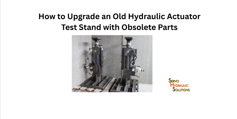
How to Upgrade an Old Hydraulic Actuator Test Stand with Obsolete Parts (Without Buying a New Machine)
November 19, 2026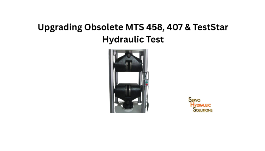
Upgrading a legacy MTS controller can bring an older hydraulic test stand back into productive service without replacing the entire machine. By replacing obsolete control electronics with a modern digital controller, laboratories can improve test control, data acquisition, software support, and long-term maintainability while retaining compatible hydraulic and mechanical components.
The right retrofit depends on the condition of the existing equipment, the type of servo valve and sensors installed, and the performance the upgraded system must deliver. An MTS 458, MTS 407, or TestStar II installation should therefore be assessed as a complete test system before selecting replacement hardware.
Why Upgrade a Legacy MTS Controller?
Many laboratories still operate hydraulic test stands that were installed years ago. The frames, actuators, grips, load cells, and hydraulic power units may remain mechanically sound, but the original controller can become difficult to maintain.
This creates an awkward situation: the machine itself is useful, yet an electronics fault or unavailable replacement board can interrupt testing.
Common Problems With MTS 458 and 407 Controllers
Older MTS 458 and 407 control systems may present several maintenance challenges, depending on their configuration and service history.
Common issues include:
- Ageing electronic boards and power supplies.
- Failed or difficult-to-source components.
- Limited availability of specialist repair support.
- Older interfaces and communication hardware.
- Restricted options for modern data acquisition.
- Dependence on legacy software and operating environments.
- Difficulty integrating newer sensors or test equipment.
Not every installation has all these problems. A working controller should not be replaced simply because it is old. The decision should be based on component condition, supportability, test requirements, and the cost of maintaining the existing system.
Limitations of TestStar II Systems
TestStar II systems were developed around the control hardware and software architecture available at the time of their installation. Some laboratories continue to use them successfully, but ageing computers, interface cards, operating systems, and peripheral equipment can make maintenance increasingly difficult.
Typical concerns include:
- Older computer hardware and operating-system dependencies.
- Limited compatibility with current data systems.
- Difficulty sourcing replacement interface components.
- Challenges transferring test data into modern workflows.
- Dependence on specialised legacy software configurations.
A TestStar II-to-modern-PC controller retrofit should address both control functionality and the laboratory’s data workflow. Replacing the computer alone does not guarantee that the original control functions will operate correctly.
Risks of Continuing With Obsolete Controls
Keeping an obsolete controller running may appear cheaper than upgrading, particularly when the machine still performs routine tests. The problem is the uncertainty surrounding future failures.
A failed control board can lead to extended downtime if a replacement is unavailable. Older computers may also become difficult to maintain, while limited software support can complicate test reporting and data management.
Another concern is that the laboratory may become dependent on a shrinking pool of specialists who understand the original hardware.
Before continuing with an ageing system, consider:
- Availability of replacement parts.
- Cost and time required for repairs.
- Consequences of unexpected downtime.
- Compatibility with current test methods.
- Availability of technical support.
- Safety and control-system condition.
Benefits of a Modern Digital Retrofit
A properly engineered digital retrofit can provide:
- Modern digital closed-loop control and updated data acquisition and sensor integration make test results easier to organize, analyze, and export..
- Improved access to test parameters and feedback signals.
- Updated data acquisition and test reporting.
- Easier integration with current computers and networks.
- Better access to replacement components.
- Reduced dependence on obsolete electronic assemblies.
- Opportunities to expand test capabilities.
The improvement depends on the controller, software, sensors, and integration quality. When servo valve amplifiers or other rig hardware are also ageing, upgrading legacy hydraulic actuator test stands with COTS parts can extend service life further, though a digital controller does not automatically improve the mechanical performance of an actuator or hydraulic power unit that is already worn or undersized.
What Is a Drop-In Digital Retrofit?
A drop-in digital retrofit replaces obsolete control electronics while retaining suitable parts of the original hydraulic test stand. The objective is to modernize the control system without undertaking an unnecessary complete machine replacement.
The term “drop-in” should be used carefully. A retrofit may reduce mechanical changes, but electrical interfaces, signal conditioning, wiring, software, and safety circuits often require modification.
How a Drop-In Controller Retrofit Works
The process begins with an inspection of the existing system.
Engineers identify the controller architecture, actuator type, servo valve, feedback sensors, power supplies, wiring, safety circuits, and hydraulic equipment. The replacement controller is then configured to work with the verified components.
A typical retrofit involves:
- Documenting the existing control system.
- Identifying input and output signals.
- Checking sensor and servo valve compatibility.
- Designing interface electronics and wiring.
- Installing the replacement controller.
- Configuring control loops and test software.
- Calibrating feedback channels.
- Testing safety functions and system response.
The goal is to preserve useful equipment while replacing the parts that limit reliability or supportability.
What Can Be Replaced During an Upgrade?
Depending on the original installation, an upgrade may replace:
- Analogue controller electronics.
- Obsolete digital control boards.
- Legacy computer hardware.
- Interface and communication cards.
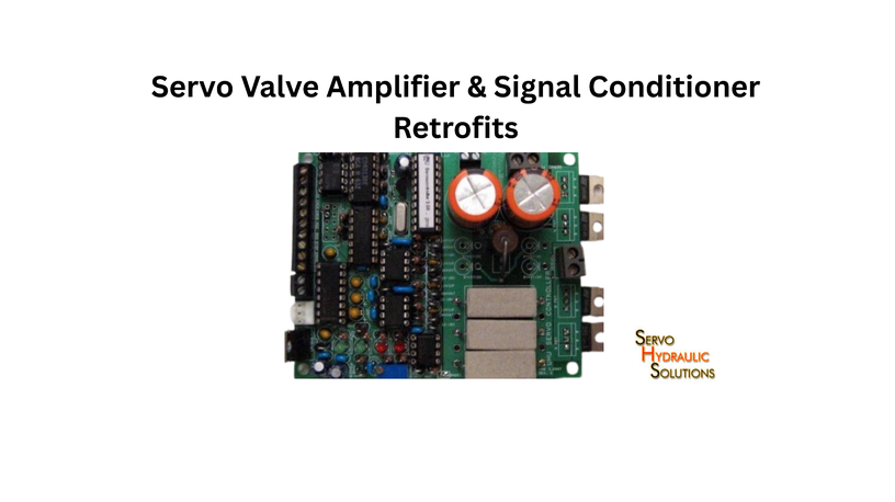
- Signal-conditioning modules.
- Data acquisition hardware.
- Control software and operator interfaces.
- Selected electrical cabinets and wiring.
The replacement scope should be based on an equipment audit, not a standard parts list.
What Can Be Retained From the Existing Test Stand?
Many installations contain components that remain serviceable.
Potentially reusable items include:
- Load frames and structural assemblies.
- Hydraulic actuators.
- Hydraulic power units.
- Servo valves.
- Load cells.
- LVDTs and displacement transducers.
- Pressure sensors.
- Grips, fixtures, and specimen mounting hardware.
Inspect each component and check it against the new controller’s requirements. Age alone does not make a component unsuitable, but previous operation does not prove it is safe or accurate today.
Drop-In Retrofit vs Full System Replacement
| Consideration | Digital retrofit | Full system replacement |
| Existing frame | Usually retained if suitable | Replaced or redesigned |
| Hydraulic equipment | May be reused | Usually selected as part of new system |
| Controller | Replaced | New controller supplied |
| Installation work | Focuses on control integration | Covers the complete installation |
| Initial investment | Often lower | Usually higher |
| Downtime | Depends on retrofit complexity | Depends on new installation |
| Main challenge | Compatibility with legacy components | Full procurement and commissioning |
A retrofit is attractive when the mechanical and hydraulic equipment remains in good condition. If the frame, actuator, or hydraulic system is also unsuitable, replacing only the controller may postpone the problem rather than solve it.
Replacing Obsolete MTS 458 Analogue Controllers
Replacing obsolete MTS 458 analogue controllers requires careful attention to the original signal architecture. The new digital system must reproduce the required control behaviour while maintaining compatibility with the existing actuator and feedback equipment.
How the MTS 458 Controller Works
An analogue hydraulic controller typically processes command and feedback signals to regulate actuator movement. Depending on the installation, these signals may include displacement, force, or other measured quantities.
The controller compares the command with the measured response and adjusts the servo valve drive to reduce the difference.
The exact signal arrangement and control functions vary between installations. Therefore, the original wiring diagrams, controller documentation, and machine configuration should be reviewed before designing a replacement.
Common 458 Controller Upgrade Requirements
A replacement controller may need to support:
- Required control modes, such as displacement or force control.
- Existing sensor input ranges.
- Servo valve command requirements.
- Feedback signal conditioning.
- Limit detection and interlocks.
- Test waveform generation.
- Data acquisition and reporting.
The upgrade should also establish which original functions are essential and which can be improved or simplified.
Interface Compatibility and Signal Mapping
Signal mapping is one of the most important parts of an MTS 458 retrofit.
The engineering team should identify every relevant input and output, including:
- Command signals.
- Feedback signals.
- Servo valve drive signals.
- Load cell outputs.
- Displacement transducer outputs.
- Pressure measurements.
- Limit switches.
- Emergency stop and safety signals.
Signal voltage, current, polarity, scaling, grounding, shielding, and connector arrangements must be checked.
A signal that appears electrically compatible may still have the wrong scaling or response characteristics. Incorrect mapping can produce unstable control, inaccurate measurements, or unexpected actuator movement.
Servo Valve and Actuator Compatibility
You may be able to reuse the original servo valve, but you must verify its electrical requirements and hydraulic condition.
Check the valve’s drive type, rated current, input characteristics, electrical connections, and required signal conditioning. Also inspect the actuator and mechanical connections—including low-backlash joints and bearings—for leakage, friction, seal condition, and mechanical wear.
The replacement controller must be configured for the actual actuator-valve combination. Qualified personnel should tune the control loop under controlled conditions.
Safety Interlocks and Emergency Stop Integration
Safety circuits must be treated as a separate engineering requirement, not as an optional part of the controller replacement.
Review emergency stops, travel limits, pressure protection, hydraulic shutdown, guarding, and other machine-specific safety functions.
The retrofit should document how each safety function operates and verify it during commissioning. A new software interface must never bypass or unintentionally weaken existing protective arrangements.
MTS 407 Digital Controller Upgrade
An MTS 407 digital controller upgrade can modernise the control electronics while retaining compatible mechanical and hydraulic equipment. The exact scope depends on the version, installed options, and condition of the existing test stand.
How the MTS 407 Controller Works
The MTS 407 controls hydraulic test systems. It coordinates command signals, feedback measurements, and actuator control to perform the required test.
Because installations can differ, the controller’s exact configuration should be established from its hardware identification, documentation, wiring, and existing operating setup.
Common 407 Controller Upgrade Requirements
A typical upgrade assessment considers:
- Existing control modes and test requirements.
- Sensor types and signal ranges.
- Servo valve electrical characteristics.
- Controller input and output requirements.
- Data acquisition needs.
- Safety and interlock arrangements.
- Software and operator-interface requirements.
The aim is to reproduce the necessary test functions and provide a maintainable platform for future use.
Replacing 407 Control Electronics
The replacement may include digital control hardware, signal-conditioning modules, interface boards, computer hardware, and software.
A wiring and interface plan should be prepared before installation. This helps identify which original connections can remain and which require new terminals, cables, or isolation.
The replacement should also include a documented configuration backup so that future maintenance does not depend on undocumented settings.
Retaining Hydraulic Components and Sensors
A controller upgrade does not automatically require a new hydraulic power unit or actuator.
Existing equipment may be retained if inspection and testing confirm that it remains suitable. Load cells, LVDTs, pressure transducers, and servo valves should be checked for condition, calibration, electrical compatibility, and performance.
If an existing sensor has an unsuitable output range or unreliable signal, replacement may be more practical than adapting the new controller around it.
DAQ and Software Upgrade Options
Modern data acquisition can make test results easier to organise, analyse, and export.
Depending on the application, an upgrade may provide:
- Additional measurement channels.
- Configurable sampling rates.
- Live test monitoring.
- Automated data logging.
- Export to standard data formats.
- Improved test reports.
- Integration with laboratory data systems.
Select the required sampling rate and measurement accuracy based on the test method and expected signal behaviour.
TestStar II to Modern PC Controller Retrofit
A TestStar II to modern PC controller retrofit can address ageing computer hardware and software limitations while updating the control and data workflow. It requires more than installing a new computer: the controller hardware, interfaces, feedback channels, and test procedures must work together.
How TestStar II Systems Work
TestStar II installations combine control hardware, computer-based software, and interfaces to operate hydraulic testing equipment.
The system receives test commands, processes feedback, and regulates actuator behaviour through the connected hydraulic control equipment.
Different installations may have different hardware and software configurations. The existing system should be documented before selecting a replacement architecture.
Common TestStar II Upgrade Requirements
Common project requirements include:
- Replacing obsolete computer hardware.
- Updating control electronics.
- Replacing unsupported interface cards.
- Retaining compatible hydraulic components.
- Recreating essential test procedures.
- Improving data storage and export.
- Maintaining required control and safety functions.
The laboratory should identify which existing test methods must continue operating after the upgrade.
Moving From TestStar Software to Modern Control Software
Moving to a modern PC-based controller may involve configuring a new operator interface and rebuilding test sequences.
Do not assume that old software files will run directly on the replacement platform. You may need to recreate or convert test procedures, calculations, limits, and reporting formats.
Before migration, record representative test settings and expected outputs. These provide a useful reference when verifying the new software.
Data Migration and Calibration Transfer
Preserve existing test data in accessible formats wherever possible.
Calibration information also needs careful handling. Record sensor identification, calibration factors, engineering units, ranges, and calibration dates.
Calibration values should not simply be copied into a new system without verification. The new signal-conditioning and scaling arrangements may differ from the original configuration.
Network, DAQ, and Remote Access Upgrades
A modern PC controller may support improved data transfer, network storage, and laboratory reporting.
However, remote access should be designed with suitable access controls and operational safeguards. Network connectivity must not allow unauthorised users to initiate machine movement or interfere with active tests.
Keep control-system access separate from general office network access where the risk assessment and system architecture require it.
COTS Digital Controller Retrofit for Legacy Test Stands
A COTS digital controller retrofit uses commercially available control hardware and software to modernise an existing test stand. The components may include digital controllers, industrial computers, signal-conditioning modules, interface hardware, and data acquisition equipment.
What Is a COTS Digital Controller?
COTS means commercially available off-the-shelf. These are standard products you can buy from established component manufacturers rather than develop entirely for one machine.
For hydraulic test stands, a COTS controller can provide digital control functions, measurement inputs, actuator command outputs, and software interfaces.
The controller still needs application-specific configuration and integration.
Benefits of COTS Retrofit Components
A well-selected COTS architecture can offer:
- Better access to replacement hardware.
- Reduced dependence on obsolete boards.
- More flexible data acquisition.
- Easier integration with modern computers.
- Expandable input and output channels.
- Better long-term component support.
- Greater flexibility in software and reporting.
The value comes from selecting components with documented specifications and a realistic support path.
Limitations of COTS Systems
Standard components are not automatically compatible with every legacy MTS installation.
Potential problems include different signal levels, servo valve drive requirements, feedback characteristics, communication protocols, and control-loop performance.
A low-cost controller may also lack the processing speed, synchronisation, or specialised control functions needed for demanding tests.
When Custom Interface Engineering Is Needed
Custom interface engineering may be required when the original machine uses unusual wiring, signal conditioning, connectors, or valve-drive arrangements.
Engineers may need to develop interface circuits, isolation, signal scaling, protective circuits, and custom wiring assemblies.
This is where a retrofit specialist adds value. The goal is not simply to make connectors fit; it is to establish reliable electrical and control behaviour.
How to Avoid OEM Lock-In
OEM lock-in occurs when continued operation, maintenance, or expansion depends heavily on proprietary hardware, software, or specialist support from the original manufacturer.
A COTS retrofit can reduce this dependence by using documented, commercially available components and accessible system interfaces.
Before selecting a replacement, ask for:
- Hardware specifications and documentation.
- Access to configuration and calibration files.
- Clear software licensing terms.
- Availability of replacement components.
- Wiring and interface drawings.
- Training and maintenance documentation.
A modern system should be maintainable by suitably qualified technicians without unnecessary dependence on a single supplier.
How to Plan an MTS Controller Upgrade
A successful retrofit begins with an accurate picture of the existing machine. Skipping the audit stage is one of the easiest ways to create delays and unexpected costs.
Audit the Existing Test Stand
Record the controller model and configuration, frame, actuator, hydraulic power unit, servo valve, sensors, and computer hardware.
Collect available manuals, wiring diagrams, hydraulic schematics, calibration records, and previous maintenance reports.
Also document the tests the machine currently performs and the tests required after the upgrade.
Identify Sensors, Valves, and Hydraulic Components
Prepare an equipment register covering:
| Component | Information to record |
| Actuator | Type, stroke, force rating, condition |
| Servo valve | Model, drive requirements, condition |
| Load cell | Range, output, calibration |
| LVDT | Range, signal type, calibration |
| Pressure sensor | Range, output, location |
| Hydraulic power unit | Pressure, flow, cooling, condition |
| Safety devices | Function, wiring, operating condition |
This information helps establish what can be retained and what should be replaced.
Define Control and DAQ Requirements
Identify the control modes, test waveforms, measurement channels, sampling rates, and reporting requirements.
Consider whether the laboratory needs additional channels, improved test automation, or integration with external measurement equipment.
Plan Electrical, Hydraulic, and Safety Interfaces
Review the wiring, signal conditioning, valve drive, grounding, shielding, hydraulic connections, and protective circuits.
The retrofit design should show how the new controller interacts with every retained component. Independently review and verify safety functions.
Prepare a Migration and Commissioning Plan
Plan the work in stages:
- Document the original machine configuration.
- Back up available test procedures and data.
- Install the replacement control hardware.
- Verify electrical interfaces and sensor signals.
- Configure and tune the control loops.
- Check safety functions.
- Perform controlled functional tests.
- Verify measurement accuracy and system response.
- Train operators and hand over documentation.
Testing should progress from safe, low-demand checks to representative operating conditions.
Compare Retrofit Quotations
Compare quotations based on the full scope, not controller price alone.
Check whether the supplier includes:
- Existing system inspection.
- Interface design and wiring.
- Controller and software.
- Sensor and servo valve integration.
- Safety-system review.
- Installation and commissioning.
- Calibration and performance verification.
- Operator training.
- Documentation and ongoing support.
A quotation that excludes integration or commissioning may look inexpensive but leave the laboratory responsible for critical engineering work.
Conclusion
Upgrading obsolete MTS 458, 407, and TestStar II control systems can extend the useful life of hydraulic test stands when their frames, actuators, and hydraulic components remain in suitable condition. A modern COTS digital controller can replace ageing electronics, improve data acquisition, and provide a more maintainable control platform without automatically requiring a complete machine replacement.
The most important part of the project is compatibility. Servo valve requirements, sensor signals, control-loop behavior, wiring, hydraulic condition, and safety interlocks must all be assessed before choosing replacement hardware.
A well-planned drop-in digital retrofit should include an equipment audit, documented interface design, calibration verification, commissioning, and operator training. When these steps are handled properly, laboratories can modernize legacy equipment while retaining valuable existing assets and reducing dependence on obsolete control technology. To discuss controller retrofits or broader testing systems and custom shake tables, connect with our engineering team.
Frequently Asked Questions
1. What is a legacy MTS controller upgrade?
It is the replacement or modernization of ageing MTS control electronics, computer hardware, or software while retaining suitable parts of the existing hydraulic test stand. The scope depends on equipment condition and the required test functions.
2. Can an obsolete MTS 458 controller be replaced with a modern digital controller?
Yes, provided the replacement is engineered for the existing servo valve, actuator, sensors, signal interfaces, and safety circuits. Signal mapping and control-loop commissioning are essential.
3. Can an MTS 407 controller be upgraded without replacing the entire test stand?
In many cases, yes. The existing frame, actuator, hydraulic power unit, and sensors may be retained if they are in suitable condition and compatible with the new control architecture.
4. Can TestStar II be upgraded to a modern PC-based controller?
Yes. A retrofit can replace obsolete computer and control hardware with a modern platform. Review and migrate or recreate existing test procedures, interfaces, and calibration information as needed.
5. What is a drop-in digital retrofit for a legacy test stand?
A drop-in digital retrofit replaces obsolete control electronics while retaining compatible mechanical and hydraulic equipment. Some wiring, interface, and safety modifications may still be necessary.
6. What components can be retained during an MTS controller upgrade?
Depending on inspection and compatibility, the laboratory may retain the frame, actuator, hydraulic power unit, servo valve, load cell, LVDT, pressure sensors, and fixtures.
7. What components usually need to be replaced during an MTS retrofit?
Common replacements include obsolete controller boards, computer hardware, interface cards, signal-conditioning modules, and unsupported software. Wiring and electrical cabinets may also need modification.
8. Is a COTS digital controller compatible with MTS 458 systems?
It can be compatible when its inputs, outputs, signal conditioning, servo valve drive, and control functions match the existing installation. Custom interface engineering may be required.
9. Is a COTS digital controller compatible with MTS 407 systems?
Potentially, yes. Compatibility depends on the installed 407 configuration, sensor signals, valve requirements, control modes, and safety interfaces. An equipment audit is necessary before selecting a controller.
10. Can a modern controller work with existing MTS servo valves?
Yes, if the valve’s electrical drive requirements and hydraulic operating characteristics are supported by the replacement system. Inspect and test the valve before reuse.
11. Can existing sensors and transducers be reused after a controller upgrade?
Often, yes. Load cells, LVDTs, and pressure transducers can be retained when their condition, signal ranges, accuracy, and calibration are suitable for the new controller.
12. Do I need to replace the hydraulic power unit during a controller retrofit?
Not necessarily. The existing hydraulic power unit can remain if it provides the required pressure and flow and is in acceptable condition. Its performance and safety provisions should be inspected.
13. What is OEM lock-in in MTS test systems?
OEM lock-in is dependence on proprietary hardware, software, replacement parts, or specialist support from the original equipment manufacturer for continued operation and maintenance.
14. How can a COTS retrofit reduce dependence on the original equipment manufacturer?
It can replace obsolete proprietary control hardware with documented, commercially available components. Open documentation, accessible configuration files, and a clear support arrangement can make future maintenance more flexible.
15. What is the difference between a drop-in retrofit and a full system replacement?
A drop-in retrofit focuses on modernising the controller and related interfaces while retaining suitable existing equipment. A full replacement involves replacing most or all of the test system, including major mechanical, hydraulic, and control components.
Modernizing an MTS 458, 407, or TestStar II Test Stand?
Retain your sound load frames, actuators, and transducers while upgrading ageing control electronics to a modern COTS digital architecture with open documentation and dependable support.