- Have any Query
- (303) 807-1061
- doug@servohydraulicsolutions.com
How to Upgrade an Old Hydraulic Actuator Test Stand with Obsolete Parts (Without Buying a New Machine)

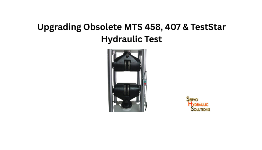
Upgrading Obsolete MTS 458, 407 & TestStar Hydraulic Test Stands with Modern COTS Digital Controllers
November 19, 2026
An old hydraulic actuator test stand can often be upgraded without purchasing a completely new machine. By replacing discontinued electronics, sourcing compatible COTS components, updating control software and servicing worn hydraulic parts, laboratories can extend the useful life of an existing test rig.
The important part is knowing what to replace and what to retain. A successful retrofit is not simply about finding a modern substitute for every obsolete component. The replacement parts must work with the existing actuator, servo valve, controller, sensors and hydraulic power unit.
Why Upgrade a Legacy Hydraulic Actuator Test Stand?
Many testing laboratories have hydraulic test stands that have operated reliably for years. The mechanical structure may still be suitable for demanding tests, but the electronics and control components can become difficult to maintain.
When a small discontinued component causes the entire machine to stop working, replacing the complete test stand may seem like the easiest option. It is not always necessary.
Common Problems With Obsolete Test Stands
Ageing hydraulic test equipment can develop several problems over time:
- Discontinued servo valve amplifiers and controller boards.
- Older computers and unsupported operating systems.
- Faulty analog signal-conditioning modules.
- Unstable sensor readings and electrical connections.
- Hydraulic leaks, worn seals and contaminated oil.
- Limited access to compatible replacement components.
- Outdated software with restricted data export options.
A particularly frustrating situation occurs when the machine is mechanically sound but cannot operate because one electronic module has failed. Finding an identical replacement may be difficult, especially when the original manufacturer no longer supports that component.
Risks of Continuing With Discontinued Components
Continuing to operate a machine with obsolete parts can increase maintenance risks.
Unexpected downtime: A failed component may take weeks to replace if it is no longer manufactured or available through normal suppliers.
Uncertain repairs: Used or refurbished electronics may have an unknown service history. They can restore operation temporarily, but their remaining service life may be difficult to predict.
Limited technical support: Engineers may struggle to obtain circuit diagrams, configuration files or troubleshooting assistance.
Compatibility problems: Replacing one component with a different model can introduce signal, wiring or control issues if the interfaces are not checked.
Safety concerns: Ageing electrical and hydraulic protection systems may not provide the level of monitoring required for the machine’s current use.
The answer is not to replace every old component automatically. It is to identify which parts are creating operational, reliability or safety risks.
Benefits of a COTS Retrofit
A retrofit using suitable commercial off-the-shelf (COTS) components can provide a practical alternative to a complete machine replacement.
Potential benefits include:
- Easier access to replacement electronics.
- Reduced dependence on discontinued proprietary hardware.
- Updated control and data acquisition capabilities.
- Improved maintenance documentation.
- Better integration with modern computers and software.
- Retention of serviceable mechanical and hydraulic equipment.
- More flexibility when planning future upgrades.
For example, a laboratory may have a test stand with a healthy actuator and hydraulic power unit but an unsupported valve amplifier. Replacing the amplifier and adapting its interface may restore operation without changing the complete hydraulic installation.
The actual savings depend on the machine’s condition, the integration work and the availability of compatible parts.
When Replacement Is Better Than Upgrade
A retrofit is not always the right investment. Consider a new machine if:
- The load-bearing frame has serious structural damage.
- The actuator has excessive wear or cannot maintain the required performance.
- The hydraulic power unit is beyond economical repair.
- The required force, stroke or frequency is outside the existing system’s capability.
- Essential components cannot be replaced or safely integrated.
- The total retrofit cost approaches the cost of a suitable replacement.
A useful decision should compare the expected service life, performance, safety and supportability of both options—not just their initial purchase prices.
What Is a Hydraulic Test Stand Retrofit?
A hydraulic test stand retrofit involves updating selected parts of an existing testing machine while retaining components that remain suitable for service.
The work may include new controller hardware, servo valve amplifiers, sensors, data acquisition systems, software and hydraulic components. The scope depends on the machine’s condition and the tests it needs to perform.
How a Hydraulic Actuator Test Stand Works
A hydraulic actuator test stand uses pressurized hydraulic fluid to create controlled force or movement.
A typical system includes:
- Hydraulic power unit: Supplies pressurized oil at the required flow and pressure.
- Servo valve: Controls the direction and amount of hydraulic flow supplied to the actuator.
- Actuator: Produces the required movement or force.
- Sensors: Measure variables such as force and displacement.
- Controller: Compares the requested test command with measured feedback.
- Software and data acquisition: Allow operators to configure tests, monitor performance and record results.
During a closed-loop test, the controller continuously processes feedback and adjusts its output to achieve the requested response.
This means every major component has a role in overall performance. A modern controller cannot compensate for an actuator with mechanical damage or a hydraulic power unit that cannot provide enough flow.
What Can Be Replaced During a Retrofit?
Depending on the assessment, a retrofit may include:
| Component | Possible upgrade |
| Controller | Replace obsolete control hardware with a supported platform |
| Servo valve amplifier | Install a compatible modern amplifier |
| Signal conditioning | Update analog input and output interfaces |
| Computer | Replace unsupported computer hardware |
| Software | Introduce maintainable control and data acquisition software |
| Sensors | Replace unsuitable or damaged measurement devices |
| Electrical cabinet | Update wiring, protection and component layout |
| Hydraulic components | Service or replace worn valves, hoses, filters and seals |
Not every project needs all these changes. A targeted upgrade can be more practical than a complete electronics replacement when most of the system remains functional.
What Can Be Retained From the Existing Stand?
A major advantage of hydraulic test stand modernization without replacement is the ability to retain proven equipment.
Potentially reusable components include:
- Structural frame and mounting arrangements.
- Hydraulic actuator and cylinder.
- Hydraulic power unit.
- Existing servo valve.
- Load cells and displacement transducers.
- Extensometers.
- Manifolds and hydraulic piping.
- Test fixtures and grips.
Each item needs a condition and compatibility assessment.
For example, existing servo valves and actuator assemblies may be mechanically serviceable but require a different amplifier interface, seal inspection, or alignment check. A load cell may still provide accurate measurements but need a compatible signal conditioner.
Physical fit alone does not establish electrical or functional compatibility.
Partial Upgrade vs Full System Replacement
A partial retrofit focuses on the components responsible for the current problem. A full system replacement changes most or all of the control and supporting equipment.
| Consideration | Partial upgrade | Full system replacement |
| Scope | Selected components | Major system components |
| Existing frame | Usually retained | May be replaced |
| Installation work | Generally more limited | Usually more extensive |
| Integration | Focused on changed interfaces | New system integration |
| Initial investment | Can be lower | Usually higher |
| Future capability | Depends on existing limits | Can be specified for new requirements |
A partial upgrade makes sense when the existing equipment can still perform the required tests. A full replacement is worth considering when the machine’s fundamental capability or condition is no longer suitable.
When a New Test Stand Is Better
A new test stand may be the more sensible option if the laboratory needs a substantially different operating range, higher performance or capabilities that the existing frame cannot support.
For example, a stand originally designed for low-frequency actuator testing may not be suitable for a new application requiring substantially higher dynamic performance. Adding modern electronics will not automatically change the mechanical and hydraulic limits.
The upgrade decision should be based on a comparison of the existing operating envelope and the laboratory’s actual test requirements.
Replacing Discontinued Servo Valve Amplifiers
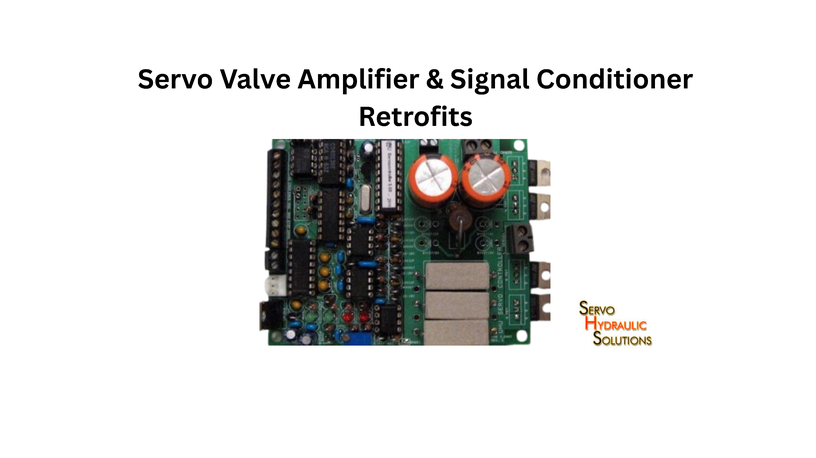
Servo valve amplifiers are among the important components to examine when upgrading older hydraulic test equipment. If the original amplifier is discontinued, a compatible replacement may allow the existing servo valve and actuator to remain in service.
However, amplifier selection requires more than matching the manufacturer’s name or connector.
How Servo Valve Amplifiers Work
A servo valve amplifier receives a command signal from the controller and supplies the electrical drive required by the servo valve.
The controller determines the requested action based on the test command and sensor feedback. The amplifier converts the controller’s output into a suitable drive signal for the valve.
The valve then regulates hydraulic flow to the actuator.
The amplifier and valve therefore have different functions:
- Servo valve amplifier: Provides the electrical drive signal.
- Servo valve: Controls hydraulic flow.
An unsuitable amplifier can prevent the valve from responding correctly, even when the valve itself is in good condition.
Common Problems With Obsolete Valve Amplifiers
Older amplifiers may develop problems such as:
- Failed electronic components.
- Unstable output signals.
- Damaged connectors or circuit boards.
- Limited adjustment or configuration options.
- Unavailable replacement modules.
- Incompatibility with modern controller outputs.
Some older units may also depend on proprietary connectors or circuit arrangements that are difficult to reproduce.
Before ordering a replacement, identify the original amplifier’s electrical characteristics and its relationship with the controller and valve.
Repair, Rebuild, or Replace: Which Option Fits?
There are three possible approaches.
| Option | Suitable situation | Main consideration |
| Repair | The fault is limited and components are available | Remaining life of repaired electronics |
| Rebuild | The amplifier has a serviceable design but needs broader restoration | Availability of components and documentation |
| Replace | The unit is unsupported, unreliable or beyond economical repair | Compatibility with the valve and controller |
Repair may be reasonable when the fault is well understood and the required components are available. Replacement may be preferable when the original design is no longer maintainable.
The decision should also consider whether the replacement can be supported over the expected service life of the test stand.
Matching a New Amplifier to the Existing Valve
This is one of the most important engineering checks.
A replacement amplifier must match the valve’s electrical and operating requirements. Check:
- Required input command signal.
- Output current or voltage range.
- Valve coil resistance and electrical characteristics.
- Connector and pin arrangement.
- Drive configuration.
- Enable and fault signals.
- Gain and adjustment requirements.
- Protection and monitoring features.
The valve’s rated flow and operating pressure should also be considered as part of the complete hydraulic system assessment.
A replacement amplifier that appears similar on paper may still have a different output arrangement. Incorrect connections or drive settings can damage equipment or produce unsuitable valve behavior.
Integrating the New Amplifier With the Controller
The replacement amplifier must communicate correctly with the existing controller.
The integration process should establish:
- The controller’s command output type and range.
- The amplifier’s accepted input signal.
- The amplifier’s output requirements.
- Enable, interlock and fault signal arrangements.
- Grounding, shielding and electrical protection.
- The correct configuration and adjustment procedure.
After installation, the system needs controlled commissioning. Engineers should verify signal direction, valve response, feedback behaviour and safe shutdown before running normal tests.
Sourcing COTS Parts for Old Test Rigs
Finding replacement components for an older test stand can take time. COTS components provide another option when original parts are no longer available, but selecting them requires a proper technical comparison.
What Is a COTS Part?
A COTS part is a commercially available component designed for use in a range of applications rather than manufactured exclusively for one machine.
Examples relevant to hydraulic test stands include:
- Industrial controller modules.
- Signal-conditioning units.
- Servo valve amplifiers.
- Pressure transducers.
- Displacement sensors.
- Data acquisition hardware.
- Industrial power supplies.
- Electrical protection devices.
A COTS component may be suitable for a retrofit, but it is not automatically a direct replacement for the original part.
Benefits of COTS Components
Sourcing COTS parts for old test rigs can offer several practical advantages.
Broader availability: Standard industrial components may be easier to source than discontinued proprietary modules.
Replacement flexibility: Laboratories may have more than one supplier option for common component types.
Improved documentation: Supported products often have current technical datasheets and installation information.
Easier maintenance planning: Standard components can make future replacement and service planning more straightforward.
Reduced dependence on legacy hardware: A well-designed retrofit can reduce reliance on a single discontinued component family.
These advantages are most useful when the selected parts have a clear support path and documented compatibility.
Limitations of COTS Systems
COTS does not mean plug-and-play.
A commercially available controller or amplifier may have different electrical characteristics, communication protocols or configuration requirements from the original equipment.
Other limitations can include:
- Additional interface electronics.
- Custom wiring or cabinet changes.
- Software integration work.
- Different adjustment procedures.
- Training requirements.
- Limited compatibility with existing sensors or valves.
The cost of integration should be included when comparing COTS components with original replacement parts.
How to Identify Compatible Replacements
Start with the original component’s model number, datasheet and wiring information.
Then compare the replacement against the actual operating requirements.
For electronic components, check:
- Supply voltage.
- Input and output signal ranges.
- Current and voltage ratings.
- Connector and pin configuration.
- Communication interface.
- Environmental operating limits.
- Fault and protection functions.
For hydraulic components, check:
- Pressure rating.
- Flow capacity.
- Port size and connection type.
- Fluid compatibility.
- Temperature range.
- Sealing materials.
- Mounting dimensions.
A replacement should meet the functional requirements of the original application, not simply look similar or share a product category.
When Custom Interface Engineering Is Needed
Custom engineering may be necessary when a modern component cannot connect directly to the original equipment.
For example, an older controller may produce an analog command signal while a replacement amplifier expects a different input range. A suitable signal interface may be required.
Other examples include:
- Adapting connectors and wiring.
- Converting or conditioning sensor signals.
- Matching valve-drive outputs.
- Integrating controller communication.
- Updating electrical cabinet layouts.
- Connecting existing safety circuits to new hardware.
Any interface must be designed so it does not introduce unacceptable signal delay, noise or control limitations.
How to Avoid OEM Lock-In
A retrofit should make future maintenance easier, not create another unsupported system.
Useful procurement requirements include:
- Standard, documented hardware interfaces.
- Accessible electrical drawings.
- Clear controller configuration records.
- Exportable test data.
- Defined software licensing terms.
- Availability of replacement components.
- Documented maintenance and troubleshooting procedures.
Ask suppliers whether the laboratory will receive the configuration files, wiring diagrams and documentation needed to maintain the upgraded system.
Hydraulic Test Stand Modernization Without Replacement
A modernization project can be divided into smaller work packages. This makes it easier to control cost, schedule installation and identify which components genuinely need attention.
Upgrade the Controller and Software
The controller and software determine how the test stand receives commands, processes feedback and manages test sequences.
A modern control platform—such as modern digital controller retrofits used to replace ageing electronics—may improve configuration, monitoring and data handling. Before selecting it, confirm that it supports the required control modes, sampling performance, sensor inputs and valve-drive interfaces.
Do not choose software based only on its user interface. The control hardware must be suitable for the machine’s dynamic requirements.
Replace Obsolete Valve Amplifiers
If the original servo valve amplifier is discontinued, identify a suitable replacement with compatible input and output characteristics.
The upgrade may also require changes to wiring, signal conditioning or controller configuration.
After installation, verify the amplifier’s operation with the valve under controlled conditions. The goal is predictable, stable valve response within the machine’s operating limits.
Update Sensors and Data Acquisition
Old sensors may still work, but their accuracy and reliability should be confirmed.
Potential upgrades include:
- Load cells.
- Displacement transducers.
- Pressure sensors.
- Extensometers.
- Data acquisition modules.
Check measurement range, sensitivity, calibration and signal compatibility before retaining or replacing a device.
The DAQ system should record the channels and sampling rates required by the laboratory’s test methods.
Service or Replace Hydraulic Components
Electronics are only one part of the machine. The hydraulic system needs its own inspection.
Review the condition of:
- Hydraulic pumps.
- Filters.
- Hoses and fittings.
- Manifolds.
- Actuator seals.
- Pressure-control components.
- Hydraulic fluid.
Oil cleanliness is particularly important for servo valves because contamination can affect their operation. Follow the component manufacturer’s filtration and fluid requirements rather than applying one general specification to every system.
Upgrade Electrical Cabinet and Safety Circuits
An older cabinet may contain crowded wiring, poorly labelled connections or components that are difficult to maintain.
A retrofit can provide an opportunity to improve:
- Component arrangement.
- Wiring identification.
- Electrical protection.
- Grounding and shielding.
- Emergency-stop integration.
- Interlock monitoring.
- Fault indication.
Safety functions must be assessed and validated as part of the completed installation. Replacing the main controller does not automatically make the machine safe.
Improve Test Automation and Data Export
Modernization can also make daily testing easier.
Depending on the software and controller, improvements may include reusable test sequences, automated data recording, digital reports and export to commonly used file formats.
For laboratories handling repeated tests, consistent test configuration can reduce manual setup and improve record keeping.
The required automation should be defined before selecting software. A system designed mainly for data collection may not provide the real-time control functions needed for a hydraulic actuator test stand.
How to Plan a Hydraulic Test Stand Retrofit
A structured plan helps avoid unnecessary component replacement and reduces the risk of compatibility problems during installation.
Audit the Existing Test Stand
Record the machine’s model, configuration, capacity and operating condition.
The audit should include:
- Structural frame condition.
- Actuator and cylinder condition.
- Hydraulic power unit specifications.
- Existing controller and amplifier details.
- Sensor and transducer information.
- Current software and computer hardware.
- Available electrical and hydraulic drawings.
- Maintenance and fault history.
Photographs of component labels, connectors and cabinet layouts are useful when requesting technical proposals.
Identify Sensors, Valves, and Hydraulic Components
Prepare a component inventory before choosing replacements.
| Component | Details to record |
| Servo valve | Model, rated flow, pressure and electrical details |
| Amplifier | Input signal, output drive and supply requirements |
| Controller | Inputs, outputs and communication interfaces |
| Load cell | Capacity, sensitivity and calibration |
| Displacement sensor | Type, range and output |
| Hydraulic power unit | Pressure, flow and condition |
| Actuator | Force, stroke and operating limits |
This information gives retrofit suppliers a clearer understanding of the existing system.
Define Control and DAQ Requirements
Identify the tests the machine must perform after modernization.
Specify:
- Required force and displacement control.
- Test frequency and waveform.
- Measurement channels.
- Sampling and recording needs.
- Test sequence requirements.
- Data export formats.
- Reporting and traceability.
- Operator access and permissions.
A clear requirement list prevents unnecessary upgrades and helps suppliers propose suitable hardware.
Plan Electrical, Hydraulic, and Safety Interfaces
Before installation, document how the replacement components will connect to the existing system.
The design should cover controller signals, sensor interfaces, valve-drive outputs, hydraulic connections, electrical protection and safety circuits.
Check that the selected components can operate within the machine’s actual pressure, flow and electrical limits.
Prepare a Migration and Commissioning Plan
A practical sequence includes:
- Back up available software, settings and configuration records.
- Document existing wiring and hydraulic connections.
- Inspect components selected for reuse.
- Install replacement electronics and hydraulic parts.
- Configure controller inputs, outputs and valve interfaces.
- Verify sensor readings and calibration.
- Test emergency stops and safety interlocks.
- Conduct controlled functional and performance checks.
- Record the final configuration and train operators.
Commissioning should be gradual. Begin with safe, controlled checks before moving to more demanding test conditions. Any performance claims should be supported by measured results.
Compare Retrofit Quotations
Ask suppliers to provide itemized quotations rather than one combined upgrade price.
Compare:
- Controller and software costs.
- Servo valve amplifier replacement.
- Sensor and DAQ upgrades.
- Electrical cabinet modifications.
- Hydraulic servicing or replacement.
- Custom interface engineering.
- Installation and commissioning.
- Calibration and validation.
- Documentation and training.
- Warranty and future support.
Also ask which components will be retained, how compatibility will be established and what performance limits will apply after the retrofit.
A technically complete proposal is more useful than the cheapest quotation if it clearly defines the work, exclusions and expected outcome.
Conclusion
Upgrading legacy actuator test equipment can be a sensible way to extend the service life of a hydraulic test stand without purchasing an entirely new machine. The key is to identify obsolete components, retain equipment that remains suitable and select replacements that work with the existing hydraulic and control systems.
Replacing discontinued servo valve amplifiers, sourcing compatible COTS parts and updating controller software can address many common maintenance problems. Still, every change needs proper interface engineering, safety checks and commissioning.
A well-planned retrofit should leave the laboratory with more than a working machine. It should provide a documented, maintainable system with clearly defined operating limits and a practical route for future support. To discuss controller retrofits, testing systems, or engineered custom shake tables for your laboratory, contact our team for a technical review.
FAQs
1. Can an old hydraulic actuator test stand be upgraded without buying a new machine?
Yes. If the frame, actuator and hydraulic system remain suitable, obsolete electronics and other components can often be replaced individually. A condition and compatibility assessment is needed first.
2. What is a hydraulic test stand retrofit?
It is the process of modernizing selected parts of an existing hydraulic testing machine. Work may include controller replacement, new servo valve amplifiers, updated sensors, software and hydraulic servicing.
3. What components can be retained during a hydraulic test stand upgrade?
Potentially reusable components include the structural frame, actuator, hydraulic power unit, servo valve, load cells, displacement sensors, extensometers, manifolds and fixtures. Their condition and compatibility must be verified.
4. What components usually need to be replaced during a hydraulic test stand retrofit?
Common replacement candidates include discontinued controller boards, obsolete servo valve amplifiers, unsupported computers, faulty signal-conditioning modules, damaged sensors and worn hydraulic components.
5. Can a discontinued servo valve amplifier be replaced with a modern COTS amplifier?
Yes, provided the replacement meets the existing valve’s electrical drive requirements and can interface correctly with the controller. Custom wiring or signal-conditioning work may be necessary.
6. Can an obsolete servo valve be repaired instead of replaced?
Yes, if suitable repair services and parts are available and the valve remains within acceptable operating condition. Inspection and performance testing should determine whether repair is technically and economically sensible.
7. How do I know if my servo valve amplifier is compatible with a new controller?
Compare the controller’s output signal with the amplifier’s input requirements. Also check wiring, signal range, drive characteristics, enable signals, fault outputs and grounding arrangements.
8. What is the difference between a servo valve and a servo valve amplifier?
A servo valve controls hydraulic flow to the actuator. A servo valve amplifier supplies the electrical drive signal that operates the valve based on the controller’s command.
9. What is a COTS part in a hydraulic test stand retrofit?
A COTS part is a commercially available component that can be used in different industrial applications. Examples include controller modules, amplifiers, sensors, signal conditioners and data acquisition hardware.
10. Can COTS components be used to replace obsolete hydraulic test stand parts?
Yes. COTS components can replace suitable obsolete parts when their electrical, hydraulic, mechanical and functional requirements match the application. Some installations also need custom interface engineering and commissioning.
Need Help Retrofitting an Obsolete Hydraulic Actuator Test Stand?
Replace discontinued servo valve amplifiers, ageing control electronics, and legacy signal interfaces with documented COTS components while keeping your serviceable hydraulic and mechanical hardware.