- Have any Query
- (303) 807-1061
- doug@servohydraulicsolutions.com
Multi-Station Legacy Hydraulic Power Unit (HPU) Retrofits: Adding VFD Controls, Manifolds & Smart Interlocks

Existing Servo Hydraulic Maintenance, Troubleshooting & Field Service Guide: When to Repair vs Rebuild
November 20, 2026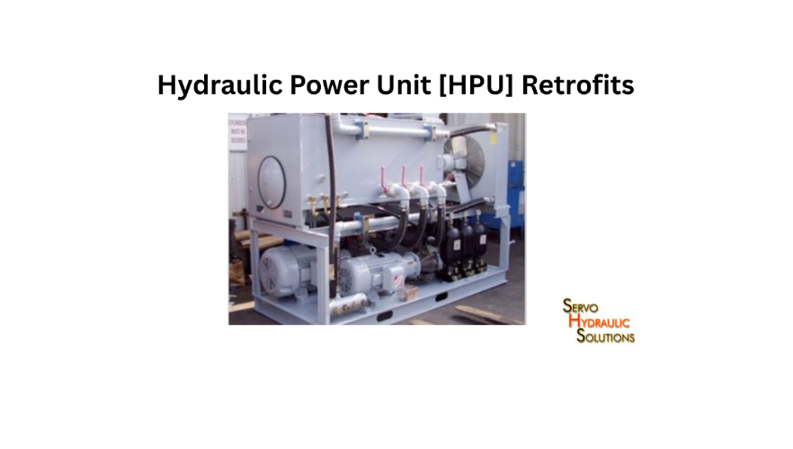
A multi-station legacy hydraulic power unit can often be modernized by upgrading its motor controls, adding suitable hydraulic manifolds and integrating smart interlocks without replacing the entire HPU. A well-planned hydraulic power supply retrofit can improve energy management, provide better control across multiple test stations and extend the useful life of existing equipment.
Many structural testing laboratories operate hydraulic power units that were installed years ago. These systems may still deliver the pressure and flow required for testing, but their electrical controls, pump arrangements and station-level safety functions may no longer meet current operating needs.
Replacing the complete HPU is not always necessary. In some cases, an upgrade involving a variable frequency drive (VFD), slow-ramp HSM manifolds and improved interlocks can address the main limitations.
The important part is understanding how the existing pump, motor, hydraulic circuit and individual test stations work together. A retrofit should improve the system without creating pressure instability, insufficient flow or unsafe operating conditions.
Why Retrofit a Legacy Multi-Station HPU?
A hydraulic power unit supplies pressurized oil to connected machines and test stations. In structural testing laboratories, one HPU may serve several servo hydraulic test stands, actuators or shake table systems.
When the original system was designed, its controls may have been intended for a smaller number of stations or a different testing schedule. Adding new equipment or increasing laboratory usage can expose those limitations.
Common Problems With Old Hydraulic Power Units
Legacy HPUs can develop several operational problems over time.
- Constant-speed operation: The pump motor may run continuously even when hydraulic demand is low.
- Limited station control: Operators may have difficulty isolating individual test stations.
- Pressure fluctuations: Changes in demand across connected stations can affect system pressure.
- High starting current: Direct-on-line motor starting can create electrical and mechanical stress.
- Ageing electrical controls: Contactors, relays, starters and control panels may become unreliable.
- Limited safety interlocks: Older systems may not provide sufficient station-level monitoring.
- Maintenance difficulties: Discontinued components and incomplete documentation can make repairs harder.
A common situation is an HPU supplying three or four test stations, with only one station operating at a time. If the pump continues running at full speed regardless of demand, energy may be used unnecessarily. The actual opportunity for improvement depends on the pump arrangement and hydraulic circuit.
Benefits of a Hydraulic Power Supply Retrofit
A properly engineered retrofit can provide several benefits:
- Improved motor control: A VFD can adjust motor speed when the pump and hydraulic circuit are suitable for variable-speed operation.
- Better station management: Manifolds can help distribute, regulate and isolate hydraulic supply to individual stations.
- Controlled pressure build-up: Suitable slow-ramp arrangements can reduce abrupt pressure application.
- Improved safety: Interlocks can prevent operation under defined unsafe conditions.
- Reduced unnecessary operation: Control changes can help match hydraulic supply to actual demand.
- Longer equipment usefulness: Serviceable pumps, motors, reservoirs and pipework may be retained.
- Easier maintenance: Updated controls and clearer station isolation can simplify fault diagnosis.
These improvements are not automatic. For example, adding a VFD does not guarantee energy savings if the pump operates against an unsuitable pressure-control arrangement.
When an HPU Retrofit Is Suitable
A retrofit is worth evaluating when:
- The pump and motor remain mechanically serviceable.
- The HPU can deliver the required pressure and flow.
- The reservoir and hydraulic distribution system are in acceptable condition.
- The laboratory wants better control over multiple stations.
- Existing electrical controls are obsolete or difficult to maintain.
- The main limitations can be addressed through targeted upgrades.
- Suitable replacement components and technical support are available.
A retrofit is particularly attractive when the existing HPU is mechanically sound but its control architecture has become outdated.
When HPU Replacement Is Better
Replacement may be the more sensible option when the pump, motor, reservoir or main hydraulic structure has deteriorated significantly.
Consider a new HPU if:
- The existing pump cannot meet the required flow or pressure.
- Repeated failures affect several major components.
- The reservoir has serious corrosion or structural damage.
- The system has persistent contamination problems.
- The hydraulic design cannot support the required number of stations.
- The cost and risk of restoring the existing unit approach those of replacement.
The comparison should include installation, piping modifications, electrical work, commissioning, and future maintenance—not just the equipment purchase price. If replacement is the right path, evaluating modern hydraulic power supplies for testing labs helps match enclosure noise control, cooling, and reservoir sizing to your lab environment.
Upgrading an Old Hydraulic Power Unit With VFD
One common improvement is upgrading an old hydraulic power unit with VFD control. A variable frequency drive adjusts the electrical frequency supplied to a compatible motor, allowing its speed to be controlled.
However, the pump and hydraulic circuit must be suitable for this operating method.
What Is a VFD in a Hydraulic Power Unit?
A VFD controls the speed of an electric motor by varying the frequency and voltage supplied to it.
In an HPU, the motor typically drives a hydraulic pump. Changing motor speed can change pump delivery, although the relationship depends on pump displacement, efficiency and operating conditions.
For a fixed-displacement pump, flow is approximately proportional to rotational speed:
[
Q \approx D \times N \times \eta_v
]
Where:
- (Q) = delivered flow.
- (D) = pump displacement per revolution.
- (N) = rotational speed.
- (\eta_v) = volumetric efficiency.
This is a simplified relationship. Actual delivery also depends on pressure, leakage, oil viscosity and pump condition.
How a VFD Improves Legacy HPU Operation
A suitable VFD can provide:
- Controlled motor starting and stopping.
- Adjustable operating speed.
- Reduced starting current compared with direct-on-line starting.
- Controlled acceleration and deceleration.
- Potential reduction in energy consumption during lower-demand periods.
- Improved motor status and fault monitoring.
For example, consider a laboratory where hydraulic demand varies between testing sessions. A properly designed variable-speed system may reduce pump speed during periods of lower demand instead of operating continuously at full speed.
The energy benefit depends on the pump type, pressure requirements, control strategy and duration of reduced demand. Establishing energy-efficient servo-hydraulic operation requires a proper engineering assessment of your actual duty cycle rather than assuming savings from the VFD’s presence alone.
Matching VFD, Motor, and Pump Requirements
The VFD must be selected for the actual motor and operating conditions.
Important checks include:
| Component | What to verify |
| Electric motor | Rated voltage, current, frequency, power and speed |
| Pump | Type, displacement, rated speed and pressure limits |
| VFD | Current capacity, overload rating and control features |
| Cooling | Motor and drive cooling at reduced speed |
| Hydraulic circuit | Pressure regulation, unloading and relief arrangements |
| Operating range | Minimum and maximum permitted motor speeds |
A fixed-displacement pump may be suitable for variable-speed operation in some circuits, but reducing speed does not always reduce hydraulic power demand safely or efficiently.
For pressure-compensated or variable-displacement pumps, the control strategy needs particular attention. The VFD should not conflict with the pump’s existing pressure or displacement control.
Electrical Requirements for VFD Retrofits
A VFD installation involves more than replacing a motor starter.
The electrical assessment should cover:
- Incoming supply voltage and available capacity.
- Motor cable sizing and insulation suitability.
- Protective devices and short-circuit coordination.
- Earthing and bonding.
- Electromagnetic interference (EMI) and cable shielding.
- Motor thermal protection.
- Drive enclosure ventilation and cooling.
- Emergency-stop and isolation arrangements.
- Compatibility with existing control panels.
Long motor cables may require additional consideration, such as output filtering, depending on the drive, motor and installation. The motor manufacturer’s recommendations should be followed.
VFD Settings and Commissioning
Commissioning should begin with verified motor and pump information.
Typical drive settings include:
- Motor rated voltage and current.
- Rated frequency and speed.
- Acceleration and deceleration times.
- Minimum and maximum speed limits.
- Motor protection settings.
- Control mode and command source.
- Fault response and restart behavior.
The commissioning team should check motor rotation, current draw, operating temperature and hydraulic pressure at different approved operating points.
A slow motor ramp does not automatically provide a safe hydraulic pressure ramp. Pressure behaviour depends on the pump, valves, accumulators, circuit volume and connected loads. Both electrical speed control and hydraulic pressure response must be verified.
Common VFD Retrofit Challenges
Some problems appear only after the system starts operating under real laboratory conditions.
| Challenge | What to investigate |
| Motor overheating at low speed | Cooling capacity and permitted speed range |
| Unstable pressure | Interaction between VFD and pressure-control circuit |
| Insufficient flow | Minimum motor speed and simultaneous station demand |
| Electrical interference | Cable routing, shielding and grounding |
| Drive trips | Motor current, acceleration settings and load conditions |
| Poor energy savings | Actual duty cycle and hydraulic unloading losses |
A VFD should be treated as part of the complete HPU control system, not as an isolated electrical accessory.
Adding Slow-Ramp HSM Manifolds to Legacy Pumps
Multi-station laboratories often need controlled hydraulic supply to several test systems. A suitable manifold arrangement can help manage station pressure, flow and isolation while reducing unwanted pressure changes during startup or station activation.
What Is a Slow-Ramp HSM Manifold?
An HSM manifold is a hydraulic supply and control manifold used in a hydraulic system. In a slow-ramp arrangement, the hydraulic circuit is designed to bring pressure up in a controlled manner rather than applying full pressure abruptly.
The exact meaning and configuration of HSM can vary between manufacturers and system designs. Therefore, the manifold’s actual schematic, valve functions and operating sequence should be reviewed before specifying a retrofit.
A slow-ramp function may use controlled valve operation, flow restriction or a dedicated pressure-control arrangement to manage how pressure is introduced.
How HSM Manifolds Improve Multi-Station Control
In a multi-station HPU, different test stands may have different operating requirements.
One station may be preparing a specimen while another is performing a dynamic test. A suitable manifold arrangement can help manage supply to each station without requiring the entire hydraulic system to be shut down.
Depending on the design, it may provide:
- Controlled pressure application.
- Station-level supply isolation.
- Pressure regulation.
- Flow distribution.
- Controlled unloading.
- Easier maintenance access.
For example, when an additional test station is connected, a properly designed manifold can allow its hydraulic supply to be introduced through a defined sequence rather than exposing the station abruptly to full system pressure.
The actual pressure ramp and flow behavior must be confirmed through hydraulic calculations and commissioning measurements.
Matching HSM Manifolds to Existing Pumps
Before adding a manifold to a legacy pump, review the complete hydraulic circuit.
Check:
- Pump type and displacement.
- Maximum rated pressure.
- Available flow.
- Pressure-control arrangement.
- Relief valve capacity.
- Oil temperature and viscosity range.
- Port sizes and connection standards.
- Expected simultaneous station demand.
- Required isolation and unloading functions.
The manifold must be rated for the system’s pressure and flow conditions. Its internal passages and valve capacity should not create excessive pressure drop or unwanted heating.
Pressure Regulation and Flow Distribution
Pressure and flow are related, but they are not interchangeable.
Pressure is the force per unit area available in the hydraulic circuit, while flow determines how quickly an actuator can move at a given displacement.
A multi-station HPU must supply enough flow for the stations expected to operate simultaneously while maintaining the pressure required by their loads.
A simplified planning calculation is:
[
Q_{\text{total}} = Q_1 + Q_2 + \cdots + Q_n
]
Where each (Q) represents the flow demand of an operating station.
The design should also account for duty cycle, peak demand, pressure losses and any diversity assumptions. Simply adding the nominal flow ratings of every connected station may overstate or understate the actual requirement, depending on the operating schedule.
Isolation and Safety Functions in HSM Manifolds
Station isolation is important when one test stand needs maintenance while others remain available.
Depending on the hydraulic design, manifold functions may include:
- Individual station shut-off.
- Pressure relief.
- Controlled unloading.
- Pressure monitoring.
- Check valves to prevent unwanted reverse flow.
- Safe depressurisation provisions.
A closed isolation valve does not necessarily mean that a station is depressurised. Trapped pressure may remain in accumulators, actuators or isolated pipe sections.
The design must include a safe method to release or verify stored hydraulic energy before maintenance.
When HSM Manifolds Are Suitable
Slow-ramp HSM manifolds may be suitable when:
- Multiple test stations share one hydraulic supply.
- Abrupt pressure application needs to be controlled.
- Individual stations require isolation.
- The existing pump has sufficient capacity.
- The manifold can be integrated without compromising pressure or flow requirements.
They are not a substitute for an undersized pump, inadequate relief protection or an unsuitable hydraulic distribution network.
Multi-Station Legacy HPU Smart Interlocks
A multi-station HPU needs more than a common start and stop command. Smart interlocks help ensure that the system operates only when defined hydraulic, electrical and station-level conditions are satisfied.
What Are Smart Interlocks in a Multi-Station HPU?
Smart interlocks are control functions that monitor operating conditions and permit, prevent or stop specific actions according to defined logic.
They may use pressure switches, temperature sensors, valve-position feedback, motor status and controller signals.
For example, a station may be prevented from enabling its test sequence until the HPU reaches the required operating pressure and the station’s isolation valve is confirmed in the correct position.
Interlocks should be designed according to the risk assessment and required safety performance. A standard programmable controller is not automatically a safety-rated controller.
Common Interlock Functions
A multi-station HPU may use interlocks for:
| Interlock function | Purpose |
| Low oil level | Prevent operation when reservoir level is insufficient |
| High oil temperature | Trigger an alarm or controlled shutdown |
| Low system pressure | Prevent testing when supply pressure is inadequate |
| Motor overload | Stop or inhibit the affected drive |
| Filter blockage | Alert operators to excessive filter restriction |
| Cooling failure | Prevent operation under unsuitable thermal conditions |
| Emergency stop | Initiate the defined emergency response |
| Station isolation | Prevent operation when supply status is incorrect |
| Accumulator pressure | Monitor stored energy and relevant operating conditions |
The response should be defined for each condition. Some faults may require an alarm, while others need an immediate controlled stop or isolation action.
How Smart Interlocks Improve Safety
Interlocks reduce the chance of equipment operating outside defined conditions.
They can prevent a test sequence from starting when a required valve is closed, oil temperature is excessive or a pressure condition is not satisfied.
For multi-station systems, station-specific interlocks also help prevent one test stand from unintentionally affecting another.
However, software logic alone is not enough. Safety functions need appropriate hardware, validated logic, fail-safe behaviour and documented testing. Emergency stops and other protective devices must be designed and verified according to the applicable safety requirements.
How Smart Interlocks Reduce Downtime
Smart interlocks can also make fault diagnosis easier.
Instead of discovering a problem after a test has started, operators may receive an alarm identifying the condition that prevented operation.
For example, a low-pressure warning can direct maintenance staff to check the HPU supply before investigating the individual test station.
Useful diagnostic features include:
- Clear alarm descriptions.
- Time-stamped fault history.
- Station-specific status indicators.
- Pressure and temperature trends.
- Drive fault information.
- Valve-position feedback.
- Maintenance alerts.
This can reduce unnecessary troubleshooting and help technicians identify the affected part of the system.
Integrating Interlocks With Existing Controllers
Legacy HPUs may use relay logic, older programmable controllers or dedicated electrical control panels.
Smart interlocks can sometimes be added while retaining suitable existing controls. The integration method depends on the available input/output channels, communication interfaces and required safety architecture.
Before implementation, document:
- Existing start and stop logic.
- Emergency-stop circuits.
- Pressure and temperature switches.
- Motor protection devices.
- Station enable signals.
- Isolation valve feedback.
- Alarm and fault-reset arrangements.
Avoid adding new logic that conflicts with existing protection. All changes should be reviewed and tested as part of the complete control system.
When Smart Interlocks Are Needed
Smart interlocks are particularly useful when:
- One HPU supplies several independent test stations.
- Operators need clear station-level status.
- Different stations have different operating requirements.
- Unintended simultaneous operation must be prevented.
- The existing control panel has limited fault diagnostics.
- Maintenance staff need better visibility of system conditions.
They are also worth considering when the laboratory is expanding its testing capacity and wants a more structured method of managing shared hydraulic resources.
How to Plan a Multi-Station HPU Retrofit
A successful retrofit starts with an accurate assessment of the existing system. Installing a VFD or manifold before understanding the pump arrangement can create problems that are expensive to correct later.
Audit the Existing Hydraulic Power Unit
Record the HPU’s current configuration, including:
- Pump manufacturer, model and type.
- Motor rating and operating speed.
- Rated pressure and flow.
- Reservoir capacity.
- Filter and cooling arrangements.
- Relief and pressure-control valves.
- Existing manifolds and distribution lines.
- Electrical starter and control panel.
- Connected test stations.
Inspect the equipment for leakage, corrosion, vibration, unusual noise and signs of overheating.
Where possible, collect operating data rather than relying only on nameplate ratings. Actual pressure, flow, temperature and motor current readings can reveal limitations that are not obvious from the original specifications.
Define Multi-Station Hydraulic Requirements
List each connected station and its operating requirements.
| Requirement | Information to collect |
| Station pressure | Required operating and maximum pressure |
| Flow demand | Continuous and peak flow |
| Duty cycle | Typical operating duration and frequency |
| Simultaneous use | Which stations may run together |
| Isolation | Whether each station needs independent shut-off |
| Pressure ramp | Whether controlled pressure application is required |
| Safety | Required alarms, trips and interlocks |
This information helps establish whether the existing pump can support the proposed arrangement.
Do not size the HPU only from the number of connected stations. Base the design on realistic simultaneous demand and the actual test programme.
Select VFD, Manifold, and Interlock Scope
Not every retrofit needs all three upgrades.
A laboratory with a suitable pump and motor but poor motor control may benefit mainly from a VFD. A system with multiple stations and limited isolation may need manifold changes. A shared HPU with weak fault monitoring may benefit from smart interlocks.
The scope should be selected according to the problems identified during the audit.
Plan Electrical and Hydraulic Integration
The electrical and hydraulic designs must be reviewed together.
For the electrical side, check the motor, VFD, protection, panel layout, wiring and control interfaces.
For the hydraulic side, verify pump capacity, pressure limits, manifold ratings, relief arrangements, line sizes, pressure drops and safe depressurization.
Also confirm that the new control logic does not interfere with existing servo hydraulic controllers or station-level safety functions.
Commissioning and Acceptance Testing
Commissioning should verify the complete upgraded arrangement.
A practical plan includes:
- Inspect new electrical and hydraulic connections.
- Confirm motor protection and VFD configuration.
- Check pump rotation and controlled startup.
- Verify pressure and flow at approved operating points.
- Test slow-ramp pressure behavior.
- Confirm station isolation and unloading.
- Verify interlock responses and alarm indications.
- Test emergency stops and protective functions.
- Check operation with the expected combination of active stations.
- Record final settings, test results and updated drawings.
Acceptance criteria should be agreed before work begins. A retrofit should not be considered complete simply because the motor starts and the system reaches pressure.
Compare Retrofit Quotations
A useful quotation should explain exactly what is being changed and what existing equipment will remain.
| Quotation item | What to confirm |
| HPU assessment | Inspection and operating measurements included |
| VFD | Drive rating, protection and configuration |
| Motor compatibility | Suitability for variable-speed operation |
| Manifold | Hydraulic schematic, pressure and flow rating |
| Slow-ramp function | Defined pressure-ramp behavior |
| Smart interlocks | Logic, sensors and safety responsibilities |
| Electrical work | Panel changes, wiring and protection |
| Hydraulic work | Piping, fittings, flushing and leak checks |
| Commissioning | Pressure, flow, interlock and operating tests |
| Documentation | Drawings, settings, manuals and test reports |
| Support | Warranty, training and future service |
Compare quotations on a like-for-like basis. A low initial price may exclude hydraulic flushing, electrical modifications, commissioning or safety verification.
Conclusion
A multi-station legacy HPU does not always need to be replaced when its controls become outdated or laboratory requirements change. A carefully engineered hydraulic power supply retrofit can retain serviceable equipment while adding variable-speed motor control, improved station distribution and more effective interlocks.
The three upgrades serve different purposes. A VFD manages motor speed, a slow-ramp HSM manifold helps control hydraulic supply to connected stations, and smart interlocks manage defined operating and safety conditions. They should be selected as parts of one coordinated system.
Before starting, assess the existing pump, motor, hydraulic circuit, station demand and control architecture. Verify the upgraded system through documented commissioning tests. This approach helps structural laboratories extend HPU life while improving maintainability, station management and operational reliability. To discuss HPU upgrades, servo-hydraulic services, or complete testing systems, connect with our engineering team.
FAQs
1. What is a multi-station legacy HPU retrofit?
It is the process of upgrading an existing hydraulic power unit that supplies multiple test stations. The work may include VFD motor controls, hydraulic manifolds, station isolation and smart interlocks while retaining suitable existing equipment.
2. What is a hydraulic power supply retrofit?
A hydraulic power supply retrofit modifies an existing HPU to improve its operation, control, safety or maintainability. It may involve electrical upgrades, pump control changes, manifold modifications and updated monitoring functions.
3. What is the benefit of upgrading an old hydraulic power unit with a VFD?
A suitable VFD can provide controlled motor starting, adjustable pump speed and potentially lower energy use when hydraulic demand varies. The actual benefit depends on pump type, motor suitability, pressure-control arrangements and operating patterns.
4. When is a VFD retrofit suitable for a legacy HPU?
It is suitable when the existing motor and pump can operate safely over the proposed speed range and the hydraulic circuit supports variable-speed control. Motor cooling, minimum speed, pressure regulation and protection settings must be assessed before installation.
5. When is HPU replacement better than a retrofit?
Replacement may be preferable when the pump, motor, reservoir or hydraulic distribution system is seriously deteriorated or cannot meet required pressure and flow. It may also be more practical when several major components need replacement and retrofit costs become excessive.
6. What is a slow-ramp HSM manifold?
It is a hydraulic manifold arrangement designed to introduce or increase hydraulic pressure in a controlled manner. Its exact valve configuration and function depend on the manufacturer’s design and the hydraulic circuit.
7. How does a slow-ramp HSM manifold improve multi-station control?
It can help manage pressure application, station isolation and hydraulic supply distribution. This allows individual test stations to be brought into operation through a defined sequence, subject to the manifold’s design and system capacity.
8. Can a slow-ramp HSM manifold be added to a legacy pump?
Yes, if the existing pump and hydraulic circuit are suitable. The manifold must be matched to the pump’s pressure and flow ratings, connection requirements, relief arrangements and expected station demand.
9. What is the difference between an HSM manifold and an ISM manifold?
HSM and ISM are not universal hydraulic industry designations with one standardised meaning across all manufacturers. Their functions depend on the supplier’s terminology and specific manifold design. Compare the hydraulic schematic, valve functions, pressure and flow ratings, isolation features and control sequence rather than relying on the abbreviations alone.
10. What are smart interlocks in a multi-station HPU?
Smart interlocks are control functions that monitor system conditions and allow or prevent specific operations based on defined logic. They may monitor oil level, pressure, temperature, motor status, station isolation and emergency-stop conditions.
11. What interlock functions are common in a multi-station HPU?
Common functions include low-oil-level protection, high-temperature alarms, low-pressure monitoring, motor overload protection, filter blockage warnings, cooling failure detection, station isolation checks and emergency-stop functions.
12. How do smart interlocks improve HPU safety?
They help prevent operation when defined conditions are not satisfied and can initiate alarms or shutdown actions when faults occur. Their safety effectiveness depends on suitable hardware, validated logic, correct installation and documented testing.
Modernizing a Multi-Station Hydraulic Power Unit?
Add VFD motor controls, slow-ramp HSM manifolds, and smart station interlocks to improve pressure stability, energy management, and lab safety without replacing a sound HPU.