- Have any Query
- (303) 807-1061
- doug@servohydraulicsolutions.com

Horizontal Slip Table Systems & Head Expanders: Extending Uniaxial Shakers for Multi-Axis Component Testing

Multi-Degree-of-Freedom (6-DOF) Hexapod vs Orthogonal Actuator
November 19, 2026
Geotechnical Shake Tables & Laminar Shear Containers: Specifying Actuators for Soil-Structure & Centrifuge Labs
November 19, 2026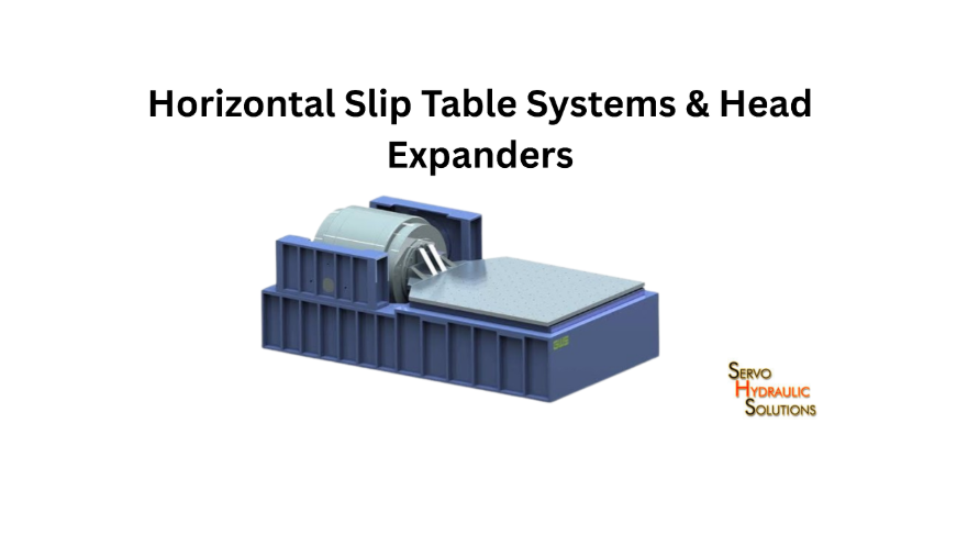
A horizontal slip table system allows a uniaxial vibration shaker to test components in the horizontal direction. At the same time, a head expander increases the available mounting area for larger or multiple specimens. Used together or separately, these accessories help laboratories extend their existing shaker capabilities without automatically investing in a completely new vibration test machine.
The important part is choosing the right configuration. Payload weight, centre of gravity, overturning moment, frequency range, bearing design, and fixture stiffness all affect test performance. A system that looks suitable on paper may behave very differently once a heavy or tall specimen is mounted.
What Is a Horizontal Slip Table System?
A horizontal slip table system is an accessory that allows a vertical-axis vibration shaker to perform horizontal vibration testing. It typically consists of a horizontal table connected to the shaker armature through a connecting arrangement, with a bearing system supporting the table and specimen.
The table moves horizontally, while the bearing assembly supports the specimen’s static weight and helps control unwanted movement. This arrangement is useful when testing components that must experience vibration along their horizontal axes.
For example, an automotive supplier may need to test an electronic control unit in three orientations. A vertical shaker setup can provide vertical excitation, but horizontal testing requires the specimen to be repositioned or the shaker to be used with a suitable slip table arrangement.
A slip table makes this possible while keeping the shaker in its intended operating orientation.
How a Slip Table Works With a Uniaxial Shaker
A uniaxial shaker produces controlled vibration along one axis. In a typical vertical configuration, the specimen is attached directly to the shaker’s armature or to a head expander mounted on it.
For horizontal testing, the shaker is connected to a slip table through a suitable drive arrangement. The shaker generates the motion, and the slip table transfers that motion to the specimen.
A typical setup includes:
- Vibration shaker: Produces the required acceleration and displacement.
- Slip table: Provides the horizontal mounting surface.
- Connecting element: Transfers motion from the shaker to the table.
- Bearing assembly: Supports the table and controls its movement.
- Specimen fixture: Holds the test component securely.
- Control and measurement system: Monitors vibration input and response.
The bearing system is particularly important because the table must move freely in the intended direction while resisting unwanted movement in other directions. Choosing the right vibration shaker technology—such as servo-hydraulic or electrodynamic—also shapes available stroke, force, and frequency performance.
Why Horizontal Testing Requires a Slip Table
Many components experience vibration from more than one direction during transportation, operation, or service. Testing only along the vertical axis may not reveal weaknesses in mounting brackets, electrical connections, housings, or internal assemblies.
A horizontal slip table helps laboratories reproduce vibration along another specimen axis without changing the fundamental shaker technology.
Common applications include:
- Automotive electronics and vehicle components.
- Aerospace equipment and onboard assemblies.
- Electrical enclosures and control panels.
- Industrial machinery components.
- Battery modules and mounting systems.
- Packaging and transportation-related testing.
The actual test orientation and vibration profile should come from the applicable product specification or test procedure. Whether you are evaluating component qualification or packaging and transportation-related testing, a slip table does not automatically reproduce every real-world multi-axis condition.
When a Slip Table System Is Needed
Consider a slip table when a laboratory needs horizontal vibration testing but already owns a compatible vertical shaker.
It can be particularly useful when:
- Specimens need testing in both vertical and horizontal orientations.
- The test programme includes heavy components that require supported horizontal mounting.
- A larger mounting surface is needed for horizontal specimens.
- The laboratory wants to extend its existing shaker’s applications.
- The required test profile is compatible with the shaker and slip table combination.
Before selecting one, check the shaker’s force, displacement, velocity, frequency range, and available reaction structure. The accessory must be matched to the complete system, not selected only by table dimensions.
What Is a Head Expander?
A head expander is a rigid fixture or mounting platform attached to a vibration shaker’s armature. Its main purpose is to provide a larger mounting surface so that bigger specimens or several smaller components can be tested.
The shaker armature is often relatively small compared with the specimen being tested. Mounting a large component directly may be impractical or create an unsuitable load distribution. A head expander adds mounting points and helps distribute the specimen load over a wider area.
Head expanders are commonly used in vertical vibration testing. Their design must account for the added mass, stiffness, mounting arrangement, and dynamic behaviour of the complete moving assembly.
How a Head Expander Extends Shaker Capability
Imagine a laboratory testing a large electrical enclosure. The enclosure has several mounting feet spread across a wide base, but the shaker armature has a much smaller mounting diameter.
A suitably designed head expander provides a larger platform with mounting holes that match the enclosure’s base. The specimen can then be secured in the required position.
It can help with:
- Mounting large or irregularly shaped components.
- Testing multiple specimens in one setup.
- Providing repeatable mounting locations.
- Distributing loads across a wider area.
- Accommodating custom test fixtures.
However, a head expander does not increase the shaker’s rated force or payload capacity. Its own mass consumes part of the available dynamic force, and its geometry can affect the system’s resonance and frequency response.
Guided vs Unguided Head Expanders
Head expanders are available in different mechanical arrangements. The right design depends on specimen size, load, operating frequency, and required support.
| Feature | Guided head expander | Unguided head expander |
| Mechanical support | Uses a guiding or support arrangement | Relies primarily on the shaker armature |
| Lateral stability | Additional guidance can improve stability | Depends heavily on armature and fixture design |
| Moving mass | May be higher due to added components | Often simpler and lighter |
| Design complexity | More complex | Generally simpler |
| Application | Larger or more demanding configurations where guidance is appropriate | Loads and dimensions within the shaker’s permitted limits |
The term guided can describe different mechanical designs, so buyers should ask the supplier exactly how the expander is supported. Additional guidance must not introduce binding, friction, or unwanted constraints that interfere with the intended motion.
When a Head Expander Is Needed
A head expander is useful when you can’t mount the specimen safely or conveniently on the standard armature.
Consider one when:
- The specimen has a wider mounting footprint.
- Several components need to be tested together.
- Multiple mounting configurations are required.
- The specimen’s mounting points do not align with the shaker interface.
- A dedicated fixture platform is needed for repeatable testing.
For tall or heavy specimens, a wider platform alone is not enough. You must also check the complete assembly for centre of gravity, overturning moment, and dynamic stability.
Slip Table vs Head Expander
Both accessories extend the capabilities of a uniaxial shaker, but they solve different problems. A slip table provides horizontal motion and support, whereas a head expander provides a larger mounting platform for testing in the shaker’s existing direction of motion.
| Comparison | Slip table | Head expander |
| Main purpose | Enables horizontal vibration testing | Increases mounting area |
| Typical orientation | Horizontal | Usually vertical |
| Main support requirement | Bearing system | Shaker armature or designed support |
| Key design concern | Bearing capacity and overturning moment | Added mass, stiffness, and resonance |
| Common use | Horizontal-axis component testing | Large or multiple specimen mounting |
Motion Direction and Test Orientation
A slip table changes the test arrangement so the specimen receives horizontal excitation. A head expander generally retains the shaker’s existing direction of motion while providing a larger mounting surface.
This difference matters when preparing a test plan. If a component needs testing along its longitudinal or lateral axis, a slip table may be appropriate. If the challenge is mounting a large component on a vertical shaker, a head expander may be sufficient.
Neither accessory independently provides simultaneous three-axis excitation.
Payload Capacity and Mounting Area
A head expander increases available mounting area, but it also adds moving mass. The shaker must accelerate the armature, expander, fixture, and specimen together.
A slip table supports the specimen through its bearing arrangement. Its capacity depends on the table, bearings, connecting mechanism, and the permitted dynamic loads.
Buyers should distinguish between:
- Maximum static supported load.
- Maximum dynamic payload.
- Maximum allowable centre-of-gravity height.
- Permitted overturning moment.
- Available mounting area.
These are separate limits. A high static load rating does not necessarily mean the system can reproduce the required acceleration with that load.
Overturning Moment and Centre of Gravity
Overturning moment is the tendency of an applied force to rotate or tilt a table or fixture around a support point.
A simple preliminary calculation is:
[
M=F\times h
]
Where:
- (M) = overturning moment.
- (F) = applied force.
- (h) = perpendicular distance from the reference point to the force line.
For an inertial load, the approximate force is:
[
F=m\times a
]
Consider a 200 kg specimen experiencing a horizontal acceleration of 5 g, with its centre of gravity 0.4 m above the reference plane.
[
F=200\times(5\times9.81)=9810\ N
]
[
M=9810\times0.4=3924\ Nm
]
This gives an illustrative inertial overturning moment of approximately 3.92 kN·m. It is not a complete design verification. Actual assessment must consider the geometry, dynamic response, fixture mass, force direction, acceleration profile, and manufacturer-defined limits.
Frequency Range and Dynamic Performance
A system’s usable frequency range depends on more than the shaker’s advertised frequency capability. The accessory, fixture, specimen, and mounting interfaces all influence dynamic behaviour.
A head expander that is too flexible may introduce resonances within the test range. A slip table with unsuitable bearing characteristics may experience friction, cross-axis movement, or waveform distortion.
The correct question is not simply, “What is the maximum frequency?” It is, “Can the complete loaded assembly reproduce the required waveform accurately across the test range?”
When to Use Both Systems
Some laboratories need both horizontal and vertical testing, along with a larger mounting surface.
In such cases, a slip table and a head expander may form part of the same broader test capability. However, they are not necessarily mounted together in every configuration. The arrangement depends on the shaker architecture, available interfaces, fixture design, and supplier-approved operating limits.
A laboratory should first define the required specimen orientations, then select compatible accessories.
Hydrostatic Bearing Slip Table for Vibration Testing
A hydrostatic bearing slip table uses a pressurised fluid film to support and guide the moving table. Instead of relying on direct sliding contact between bearing surfaces, the pressurised oil creates a thin supporting film.
This arrangement is widely considered for demanding vibration applications where low friction, smooth movement, and high load support are important.
How Hydrostatic Bearings Work
Hydrostatic bearings use an external hydraulic supply to deliver pressurised oil to bearing pockets or surfaces. The oil film separates the moving and stationary components.
In a slip table, this film supports the table while allowing controlled movement along the intended horizontal axis.
The arrangement can offer:
- Low friction during motion.
- Reduced direct contact between bearing surfaces.
- Smooth movement under suitable operating conditions.
- High load-support capability.
- Good control of table support and alignment.
The bearing design, oil pressure, flow, clearances, and table geometry all influence performance. Understanding how hydrostatic bearings support loads and maintain alignment helps determine whether a fluid-film table fits your shaker—it must still be engineered for the intended load and dynamic conditions.
Load Capacity and Overturning Moment Resistance
A horizontal slip table must support the specimen’s static weight and withstand dynamic forces during testing.
Hydrostatic bearings can distribute loads across their supporting surfaces. Their ability to resist overturning depends on bearing spacing, effective support area, pressure distribution, table stiffness, and load location.
A large specimen mounted high above the table can produce a substantial overturning moment even when its total weight is within the stated static capacity.
When reviewing specifications, request separate values for:
- Maximum static load.
- Maximum dynamic load.
- Allowable overturning moment.
- Permitted centre-of-gravity position.
- Operating displacement and velocity.
- Supported frequency range.
A supplier should confirm these limits for the intended configuration rather than relying on a general table load rating.
Cross-Axis Motion and Waveform Distortion
A slip table is designed to move along one horizontal axis. Unwanted motion in other directions can affect test accuracy.
Cross-axis motion refers to movement perpendicular to the intended excitation direction. It may result from bearing alignment problems, structural flexibility, uneven loading, fixture resonance, or excessive overturning loads.
Waveform distortion can also occur when the table and specimen do not respond as expected to the shaker input. Friction, mechanical looseness, structural resonances, and control-system limitations can contribute.
For demanding tests, engineers should evaluate acceleration in the intended axis and monitor transverse responses using suitable sensors. Testing should confirm performance under representative loading conditions.
Hydrostatic vs Mechanical Bearing Slip Tables
| Feature | Hydrostatic bearing | Mechanical bearing |
| Support principle | Pressurised fluid film | Rolling or mechanical contact arrangement |
| Friction | Very low under correct operating conditions | Depends on bearing type and loading |
| Load support | Can support substantial loads through designed pressure areas | Depends on bearing size and construction |
| Supply requirement | Requires a suitable hydraulic oil supply | Usually does not require a hydrostatic oil supply |
| Maintenance | Oil cleanliness, pressure, filtration, and leakage checks | Bearing condition, lubrication, and wear checks |
| Design considerations | Oil-film stability, clearances, and supply reliability | Contact stress, friction, wear, and alignment |
The better option depends on the application. A hydrostatic bearing may suit a high-load system requiring smooth movement, while a mechanical bearing arrangement may be adequate for a less demanding application.
Hydraulic Supply and Maintenance Requirements
Hydrostatic bearings need a reliable oil supply. The system may include a hydraulic power unit, pump, filtration, pressure regulation, reservoir, cooling arrangement, and monitoring instruments.
Maintenance should cover:
- Oil cleanliness and filter condition.
- Supply pressure and flow.
- Oil temperature.
- Leakage and hose condition.
- Bearing alignment and operating clearances.
- Abnormal noise or changes in table movement.
The bearing supply must operate within the manufacturer’s specified limits. A pressure interruption or contaminated oil can affect the bearing film and potentially damage critical surfaces.
Matching Head Expanders to Payloads
Matching head expanders to payloads is not simply a matter of choosing a platform that is large enough. The expander must work within the shaker’s force, displacement, velocity, and frequency limits while maintaining acceptable dynamic performance.
A lightweight, stiff expander is often desirable, but it must also provide sufficient strength and mounting rigidity.
Calculate Total Moving Mass
Start by calculating the complete moving mass:
[
m_{total}=m_{armature}+m_{expander}+m_{fixture}+m_{specimen}
]
For example:
| Component | Illustrative mass |
| Shaker armature | 15 kg |
| Head expander | 25 kg |
| Fixture | 10 kg |
| Specimen | 50 kg |
| Total moving mass | 100 kg |
The shaker must accelerate this entire assembly, not just the specimen.
Match Head Expander Mass to Shaker Force
A basic estimate of the force required for sinusoidal acceleration is:
[
F=m\times a
]
If the total moving mass is 100 kg and the required acceleration is 5 g:
[
F=100\times(5\times9.81)
]
[
F=4905\ N
]
The estimated inertial force is 4.905 kN. This is a simplified calculation, not a final shaker selection value. The supplier must account for the shaker’s actual force ratings, dynamic behaviour, displacement, velocity, frequency, and other operating constraints.
A heavy expander can use a significant portion of the available force, leaving less capacity for the specimen.
Check Armature, Expander, and Payload Limits
Check the manufacturer’s limits for the complete assembly, including:
- Maximum armature load.
- Maximum moving mass.
- Expander strength and stiffness.
- Mounting bolt size and tightening requirements.
- Permitted payload dimensions.
- Maximum acceleration and displacement.
- Operating frequency range.
Do not assume that a shaker’s maximum force rating can be used at every frequency or displacement.
Consider Centre of Gravity and Overturning Moment
A specimen with a high centre of gravity can create large moments during vibration. This is especially important when the specimen is tall, unevenly loaded, or mounted away from the expander centre.
Keep the specimen’s centre of gravity as close as practical to the intended mounting centre. If an offset is unavoidable, calculate the resulting forces and moments and check them against the equipment limits.
Verify Frequency Response Under Load
The head expander, fixture, and specimen form a dynamic assembly. Its natural frequencies may affect the test response.
A resonance within the required test range can amplify motion, create uneven acceleration across mounting points, or produce results that do not represent the intended input.
Useful verification methods include:
- Modal analysis during fixture development.
- Experimental resonance checks.
- Accelerometer measurements at representative mounting points.
- Low-level preliminary sweeps where appropriate.
- Loaded system checks before full-level testing.
The final setup should be assessed with a representative specimen or a suitable mass-and-stiffness equivalent.
Multi-Axis Vibration Test Fixture Design
A good fixture does more than hold a component in place. It transfers the shaker input to the specimen without introducing unnecessary flexibility, resonance, or unwanted motion.
Multi-axis vibration testing often involves changing the specimen orientation between tests. Fixture design must support those changes while maintaining repeatable mounting conditions.
Keep the Load Path Short and Stiff
The load path is the mechanical route through which vibration force travels from the shaker to the specimen.
A long or flexible fixture can introduce unwanted movement and reduce test accuracy. Keep the arrangement compact and use suitable materials, thicknesses, ribs, and support points.
Avoid unnecessary brackets, spacers, and stacked mounting plates. Every additional interface can introduce flexibility or looseness.
Centre the Specimen and Reduce Overturning Moment
Whenever possible, position the specimen so its centre of gravity is close to the intended support centre.
This reduces unnecessary moments and helps distribute the dynamic load more evenly.
If the specimen must be mounted off-centre, document the offset and verify the resulting moment against the slip table or shaker limits.
Avoid Fixture Resonance and Cross-Axis Motion
Fixture resonance can affect the specimen’s acceleration. A fixture may appear rigid during a static inspection but still flex significantly at certain frequencies.
Engineers can use finite element analysis and experimental modal testing to identify potential problems.
Check for:
- Bending of large mounting plates.
- Local flexibility around bolt holes.
- Resonance of tall brackets.
- Uneven response across specimen mounting points.
- Unwanted transverse acceleration.
A fixture should be stiff enough for the intended test range, not merely strong enough to support the specimen at rest.
Design Mounting Points for Repeatability
Repeated tests should produce comparable mounting conditions. Use clearly defined bolt patterns, locating features, and documented tightening procedures.
Where specimens are frequently removed and reinstalled, consider:
- Standardised mounting-hole patterns.
- Locating pins or alignment features.
- Accessible fasteners.
- Clearly marked specimen positions.
- Documented bolt torque values.
These details reduce setup variation and make test results easier to compare.
Include Sensors and Safety Monitoring
Sensors help confirm that the specimen receives the intended vibration input.
Depending on the test, instrumentation may include:
- Control accelerometers.
- Response accelerometers.
- Transverse-axis monitoring sensors.
- Displacement sensors.
- Temperature sensors for relevant components.
- Pressure and flow monitoring for hydraulic systems.
Sensor placement should be determined in strict accordance with the specific testing protocol and data acquisition goals. The control sensor should not be placed where local fixture flexibility produces a misleading representation of specimen input.
Safety provisions should include secure fasteners, suitable restraints where required, cable management, emergency stops, and checks for loose or moving components.
How to Buy a Hydraulic Slip Table System
Buying a hydraulic slip table system requires more than comparing table dimensions and maximum load figures. The complete configuration must match the shaker, specimen, test profile, laboratory infrastructure, and expected operating schedule.
A structured buying process helps avoid expensive compatibility problems after installation.
Define the Specimen and Test Profile
Start with the actual testing requirement.
Prepare a specification covering:
- Specimen weight and dimensions.
- Centre-of-gravity height and position.
- Required test orientation.
- Frequency range.
- Acceleration and displacement.
- Velocity requirements, where relevant.
- Test duration and duty cycle.
- Required waveform and control accuracy.
- Fixture and mounting requirements.
Include the heaviest and most demanding specimens expected during the system’s service life, not just the first planned test.
Match Slip Table, Shaker, and Reaction Base
The slip table must match the existing shaker and its mounting arrangement.
Check the drive connection, shaker force capacity, operating frequency, displacement, table dimensions, and reaction base. The foundation and reaction structure must also withstand the forces generated during testing.
Ask the supplier to confirm compatibility in writing for the proposed configuration.
Review Bearing Type and Overturning Limits
Compare hydrostatic and mechanical bearing options based on the actual load and performance requirements.
For a hydrostatic design, review the oil supply, pressure, filtration, cooling, and maintenance requirements.
For either bearing type, request documented limits for static load, dynamic load, overturning moment, centre-of-gravity position, and operating range.
A system with a large table surface may still be unsuitable for a tall specimen if its overturning capacity is insufficient.
Compare Complete System Quotations
Compare quotations on a like-for-like basis. A lower equipment price may not include all the components needed for a working installation.
Check whether the quotation covers:
- Slip table and bearing assembly.
- Shaker connection and drive components.
- Hydraulic power unit, where required.
- Reaction base and mounting hardware.
- Control-system compatibility.
- Fixtures or standard adapters.
- Instrumentation and safety provisions.
- Installation and commissioning.
- Operator training.
- Documentation and maintenance support.
Ask for performance data under the intended payload conditions, rather than relying only on unloaded specifications. You can also review dedicated shake table components or explore broader testing systems to see how accessories integrate into a complete laboratory setup.
Plan for Installation, Training, and Maintenance
A slip table may require dedicated floor space, a suitable foundation, an electrical supply, hydraulic services, and maintenance access.
Before ordering, confirm the installation layout and service requirements. Check lifting arrangements, access routes, oil storage, ventilation, and the space needed to mount and remove specimens.
Training should cover normal operation, safe loading, bearing supply checks, fixture installation, emergency procedures, and routine maintenance.
A system is a long-term laboratory investment. Reliable support and clear operating documentation matter just as much as the initial equipment specification.
Frequently Asked Questions
What Is a Slip Table System?
A slip table system is an accessory used with a vibration shaker to perform horizontal-axis testing. It supports the specimen on a bearing arrangement while transferring controlled horizontal motion from the shaker.
What Is the Difference Between a Slip Table and a Head Expander?
A slip table enables horizontal vibration testing, while a head expander increases a shaker’s mounting area, usually for vertical testing. They serve different needs and are selected based on specimen orientation and mounting requirements.
When Is a Hydrostatic Bearing Slip Table Needed?
Consider a hydrostatic bearing slip table when the application requires low-friction movement and support for substantial loads or overturning moments. Its suitability depends on the bearing design, oil supply, test profile, and manufacturer’s performance limits.
How Do I Match a Head Expander to a Shaker Payload?
Calculate the total moving mass, including the armature, expander, fixture, and specimen. Then check the required force, displacement, velocity, frequency range, centre of gravity, and allowable moments against the shaker manufacturer’s specifications.
What Is Overturning Moment in Vibration Testing?
Overturning moment is the rotational effect produced when a force acts at a distance from a support reference point. It can cause a table or fixture to tilt and must be checked when testing heavy or tall specimens.
Why Is Centre of Gravity Important for Slip Tables?
The centre of gravity affects how the specimen’s weight and dynamic forces act on the table. A high or offset centre of gravity can increase overturning moment and influence bearing loads, stability, and vibration accuracy.
Can One Slip Table Test All Three Axes?
No. A conventional slip table provides horizontal excitation along its designed axis. Testing all three specimen axes usually requires changing the specimen orientation or using a more advanced multi-axis testing system.
Does a Slip Table Reduce Shaker Force Capacity?
The slip table and its associated moving components contribute to the dynamic load that the shaker must drive. This reduces the force available to accelerate the specimen, so the complete system must be checked against the shaker’s rated limits.
What Is Cross-Axis Motion in Vibration Testing?
Cross-axis motion is unwanted movement perpendicular to the intended excitation direction. It can result from alignment errors, structural flexibility, bearing behaviour, or fixture resonance and may affect test accuracy.
Need a Custom Horizontal Slip Table or Head Expander?
Whether you are extending an existing uniaxial shaker with a hydrostatic bearing slip table, matching a lightweight head expander to your payload, or designing high-stiffness test fixtures, our engineering team is ready to help.